**这是本文档旧的修订版!**
使用RP2040和ESP32制作的网页示波器
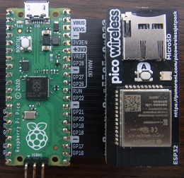
基于Pi Pico,使用ESP和MicroPython的无线网络服务器
SPI interface The ESP32 does all the hard work of connection to the WiFi network and handling TCP/IP sockets, it is just necessary to send the appropriate commands over the SPI link. In addition to the usual clock, data and chip-select lines, there is a ‘reset’ signal from the Pico to the ESP, and a ‘ready’ signal back from the ESP to the Pico. This is necessary because the Pico spends much of its time waiting for the ESP to complete a command; instead of continually polling for a result, the Pico can wait until ‘ready’ is signalled then fetch the data.
My server code uses the I/O pins defined by the Adafruit Pico Wireless Pack:
| 功能 | GPIO | 管脚编号 |
|---|---|---|
| Clock | 18 | 24 |
| Pico Tx data (MOSI) | 19 | 25 |
| Pico Rx data (MISO) | 16 | 21 |
| Chip select (CS) | 7 | 10 |
| ESP32 ready | 10 | 14 |
| ESP32 reset | 11 | 15 |
ESP32代码: The ESP32 code takes low-level commands over the SPI interface, such as connecting and disconnecting from the wireless network, opening TCP sockets, sending and receiving data. The same ESP32 firmware works with both the MicroPython and CircuitPython code and I suggest you buy an ESP32 module with the firmware pre-loaded, as the re-building & re-flashing process is a bit complicated, see here for the code, and here for a guide to the upgrade process. I’m using 1.7.3, you can check the version in CircuitPython using:
import board
from digitalio import DigitalInOut
esp32_cs = DigitalInOut(board.GP7)
esp32_ready = DigitalInOut(board.GP10)
esp32_reset = DigitalInOut(board.GP11)
spi = busio.SPI(board.GP18, board.GP19, board.GP16)
esp = adafruit_esp32spi.ESP_SPIcontrol(spi, esp32_cs, esp32_ready, esp32_reset)
print("Firmware version", esp.firmware_version.decode('ascii'))
Note that some ESP32 modules are preloaded with firmware that provides a serial interface instead of SPI, using modem-style ‘AT’ commands; this is incompatible with my code, so the firmware will need to be re-flashed.

