DDS+PWM产生任意波形
工作原理
- DDS部分
- PWM部分
- 模拟链路部分
模拟电路功能介绍
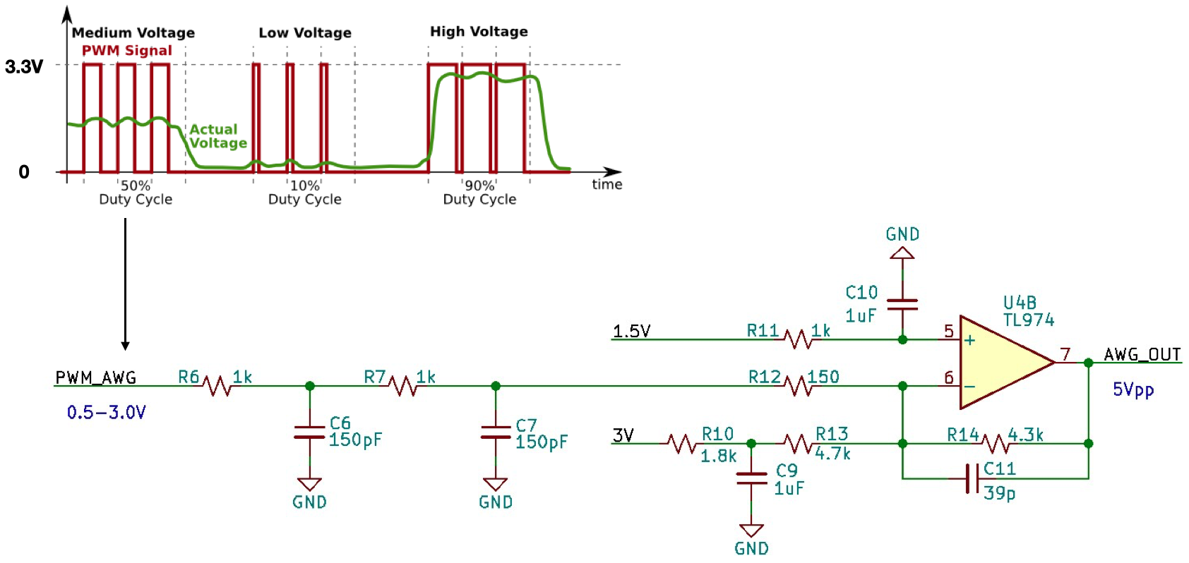
任意波形发生器模拟电路部分原理图
通过调节PWM的占空比(0.5V/3.3V ~ 3V/3.3V)得到等效幅度为0.5V - 3V之间的模拟信号,幅度变化的范围为2.5V,要得到幅度为5Vpp的模拟信号,则放大器的增益设定为G = 2: 也就是在电路原理图中放大器的增益为:R14/(R6+R7+R2) = 2 取R14 = 4.3KΩ,则R6+R7+R2 = 2.15KΩ PWM波形的中间值为(0.5V+3.0V)/2 = 1.75V,因此:
- 在PWM的输出为1.75V的时候,运算放大器的输出应为0V
- PWM的输出为0.5V的时候,运算放大器的输出为2.5V
- PWM的输出为3V的时候,运算放大器的输出为-2.5V
由此直流偏移的要求可以得到R10 + R13 = 6.5KΩ 同时R6、C6,R7、C7以及R14、C11共同构成低通滤波器。
能够生成模拟信号的最高频率 取决于PWM的主时钟频率,我们目前用的FPGA的输入时钟为12MHz,使用内部PLL以后可以得到12MHz倍数的时钟频率,最高可以到400MHz,我们取比较安全的中间值192MHz(12MHz * 16)作为PWM的主时钟。 假设DDS波表为10位精度(一般DDS信号发生器的精度,作为简易的口袋仪器,对性能指标要求不高,8位也能够满足要求),则对应于一个模拟电压值的PWM周期为192MHz/1024 = 155KHz 如果通过10个点
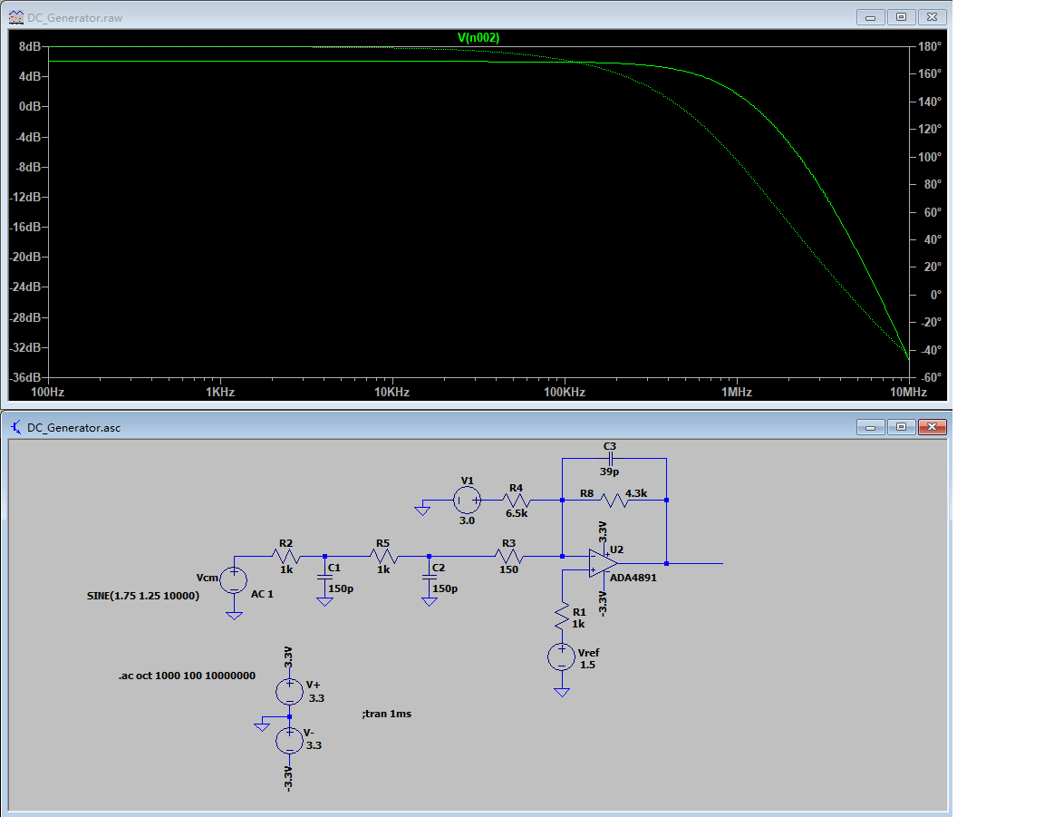
任意波形发生器模拟电路部分的仿真 - 频率响应(100Hz- 10MHz)
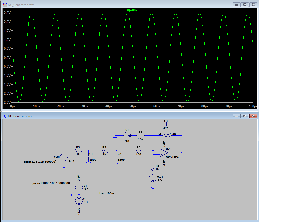
任意波形发生器模拟电路部分的仿真 - 波形(100KHz正弦波)
FPGA代码
DDS得到任意波形
相位累加器代码:
wire   	[23:0] 	next_phase;
wire   	[7:0] 	phase;
reg    	[23:0] 	accumulator;

assign next_phase = 24'H002222 + accumulator;   // set frequency = 24'H002222 / 2^24 * clock, if PLL not used, clock = 12MHz, output frequency = 6.25KHz

always @(posedge clk_hs) accumulator <= #1 next_phase;

assign phase = accumulator[23:16];   	// phase is the high 8 bits as address of the look up table

wire [9:0] sine_data;                   // sine table is 8 bit wide, 10bit resolution.

lookup_tables u_lookup_tables(phase, sine_data);
查找表代码:
module lookup_tables(phase, sin_out);
input  	[7:0] 	phase;    //sine table is 8bits wide, 10 bits resolution
output 	[9:0] 	sin_out;

wire     [9:0]   sin_out;

reg   	[5:0] 	address;
wire   	[1:0] 	sel;
wire   	[8:0] 	sine_table_out;

reg     [9:0]   sine_onecycle_amp;

//assign sin_out = {1'b0, sine_onecycle_amp[9:1]} + 9'hff;
assign sin_out = sine_onecycle_amp[9:0];

	assign sel = phase[7:6];

   	sin_table u_sin_table(address,sine_table_out);

always @(sel or sine_table_out or phase)
begin
	case(sel)
	2'b00: 	begin
			sine_onecycle_amp = 9'h1ff + sine_table_out[8:0];
			address = phase[5:0];
	     	end
  	2'b01: 	begin
			sine_onecycle_amp = 9'h1ff + sine_table_out[8:0];
			address = ~phase[5:0];
	     	end
  	2'b10: 	begin
			sine_onecycle_amp = 9'h1ff - sine_table_out[8:0];
			address = phase[5:0];
     		end
  	2'b11: 	begin
			sine_onecycle_amp = 9'h1ff - sine_table_out[8:0];
			address = ~ phase[5:0];
     		end
	endcase
end

endmodule

module sin_table(address,sin);
output [8:0] sin;
input  [5:0] address;

reg    [8:0] sin;

always @(address)
	begin
                  case(address)
                      6'h0: sin=9'h0;
                      6'h1: sin=9'hC;
                      6'h2: sin=9'h19;
                      6'h3: sin=9'h25;
                      6'h4: sin=9'h32;
                      6'h5: sin=9'h3E;
                      6'h6: sin=9'h4B;
                      6'h7: sin=9'h57;
                      6'h8: sin=9'h63;
                      6'h9: sin=9'h70;
                      6'ha: sin=9'h7C;
                      6'hb: sin=9'h88;
                      6'hc: sin=9'h94;
                      6'hd: sin=9'hA0;
                      6'he: sin=9'hAC;
                      6'hf: sin=9'hB8;
                      6'h10: sin=9'hC3;
                      6'h11: sin=9'hCF;
                      6'h12: sin=9'hDA;
                      6'h13: sin=9'hE6;
                      6'h14: sin=9'hF1;
                      6'h15: sin=9'hFC;
                      6'h16: sin=9'h107;
                      6'h17: sin=9'h111;
                      6'h18: sin=9'h11C;
                      6'h19: sin=9'h126;
                      6'h1a: sin=9'h130;
                      6'h1b: sin=9'h13A;
                      6'h1c: sin=9'h144;
                      6'h1d: sin=9'h14E;
                      6'h1e: sin=9'h157;
                      6'h1f: sin=9'h161;
                      6'h20: sin=9'h16A;
                      6'h21: sin=9'h172;
                      6'h22: sin=9'h17B;
                      6'h23: sin=9'h183;
                      6'h24: sin=9'h18B;
                      6'h25: sin=9'h193;
                      6'h26: sin=9'h19B;
                      6'h27: sin=9'h1A2;
                      6'h28: sin=9'h1A9;
                      6'h29: sin=9'h1B0;
                      6'h2a: sin=9'h1B7;
                      6'h2b: sin=9'h1BD;
                      6'h2c: sin=9'h1C3;
                      6'h2d: sin=9'h1C9;
                      6'h2e: sin=9'h1CE;
                      6'h2f: sin=9'h1D4;
                      6'h30: sin=9'h1D9;
                      6'h31: sin=9'h1DD;
                      6'h32: sin=9'h1E2;
                      6'h33: sin=9'h1E6;
                      6'h34: sin=9'h1E9;
                      6'h35: sin=9'h1ED;
                      6'h36: sin=9'h1F0;
                      6'h37: sin=9'h1F3;
                      6'h38: sin=9'h1F6;
                      6'h39: sin=9'h1F8;
                      6'h3a: sin=9'h1FA;
                      6'h3b: sin=9'h1FC;
                      6'h3c: sin=9'h1FD;
                      6'h3d: sin=9'h1FE;
                      6'h3e: sin=9'h1FF;
                      6'h3f: sin=9'h1FF;
                   endcase
              end
endmodule
调用DDS结果通过PWM生成需要的波形
//Generate AWG using 10bit resolution PWM + external RC LPF as DAC, up to 100KHz
wire [9:0] PWM_WAV_in;
assign PWM_WAV_in = sine_data[9:0];

reg [10:0] PWM_WAV_accumulator;
always @(posedge clk_hs) PWM_WAV_accumulator <= PWM_WAV_accumulator[9:0] + PWM_WAV_in;
assign pwm_awg = PWM_WAV_accumulator[10];


