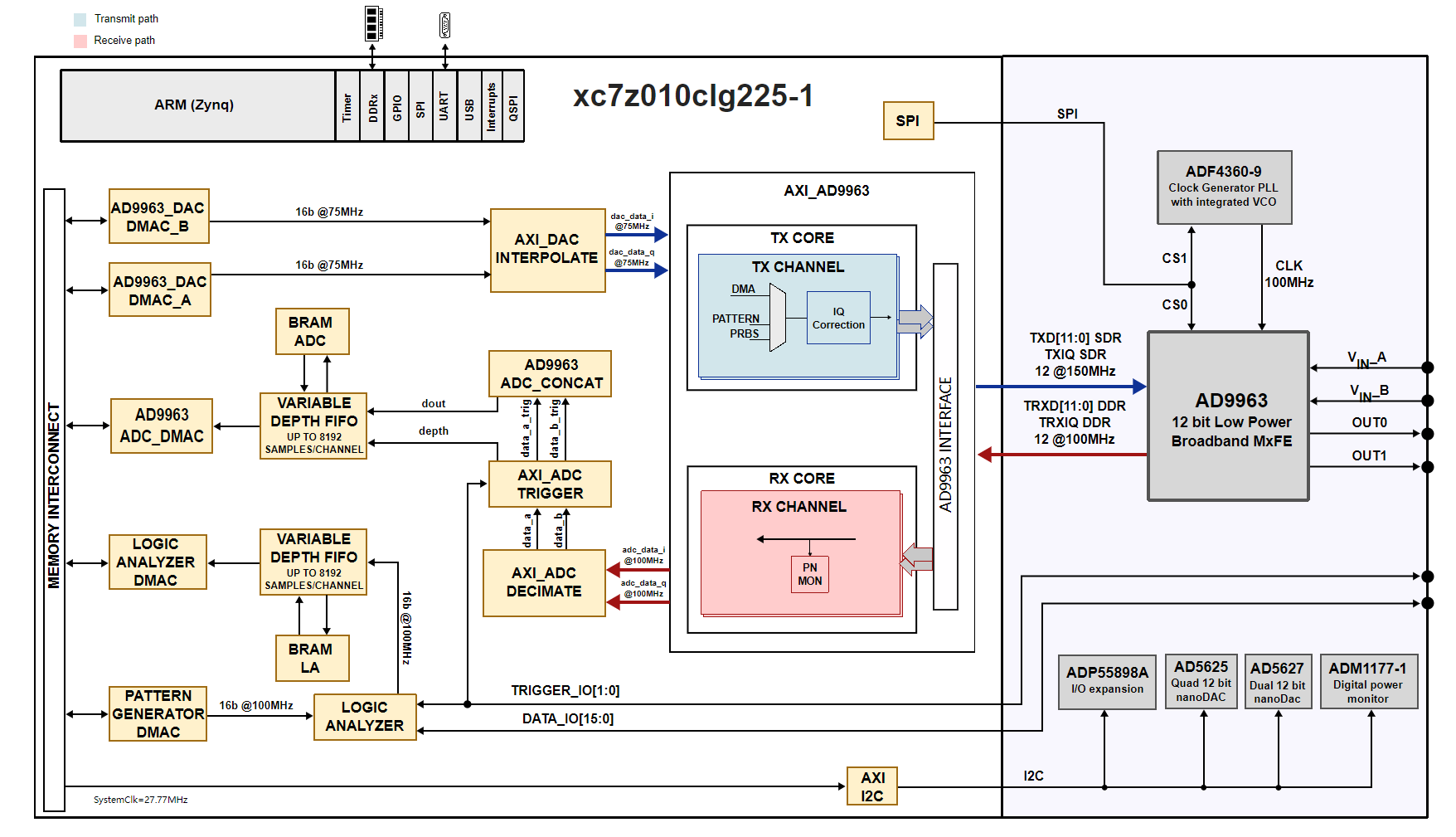
ADALM2000的FPGA设计
ADALM2000的数字信号处理部分
ADALM2000的fpga逻辑功能框图
The core of the Analog Discovery 2 is the Xilinx Spartan-6 FPGA circuit XC6SLX16-1L. The configured logic performs:
- Clock management (12 MHz and 60 MHz for USB communication, 100 MHz for data sampling)
- Acquisition control and Data Storage (Scope and Logic Analyzer)
- Analog Signal synthesis (look-up tables, AM/FM modulation for AWG)
- Digital signal synthesis (for pattern generator)
- Trigger system (trigger detection and distribution for all instruments )
- Power supplies control and instruments enabling
- Power and temperature monitoring
- Calibration memory control
- Communication with the PC (settings, status data)
Block and Distributed RAM of the FPGA are used for signal synthesis and acquisition. Multiple configuration files are available through the WaveForms software to allocate the RAM resources according to the application.
Detail of the trigger system is shown in Fig. 35. Each instrument generates a trigger signal when a trigger condition is met. Each trigger signal (including external triggers) can trigger any instrument and drive the external trigger outputs. This way, all the instruments can synchronize to each other.


