今日推荐:I2C - 集成电路之间的同步、半双工数据传输
I2C总线特性
- 除了“电源”和“地”之外,只用了“SDA”和“SCL”两根信号线
- 在同一个总线上最多可以支持到100个器件,每个挂在总线的器件都有一个地址用于寻址
- 多个“主”设备(例如,两个CPU可以简单地共用同一个I2C器件)
- 为业界标准,由Philips开发, 被很多其它厂商采用
- 用途非常广泛,比如电视机、PCs
但是:
- 速度相对比较慢(100Kbps基础速率,可以扩展到3.4Mbps)
- 不支持“即插即用”
一个I2C总线需要至少一个I2C主和I2C从. I2C“主”即可以向“从”写也可以从“从”设备中读取
I2C波形
这个图示为向地址为0x51的EEPROM进行写2个字节的数据0x50和0x0F.
一个I2C过程由“起始”开始, 接着是我们要通信的设备的地址,有一位标记此操作是“读”还是“写”;要读取或写入的“数据”,最后是个“终止”位。
还有其它的一些细节,比如在每个字节传输以后需要一个”应答“位,参看波形图。
在FPGA或CPLD中有两种方式创建一个I2C从功能:
- 直接使用你FPGA/CPLD中的SCL信号线作为时钟信号
- 使用更快的时钟信号过取样你的SDA和SCL信号
第一种方法设计比较紧凑,但不如第二种方法可靠,在这里我们简单讲一下第一种方法的实现过程。
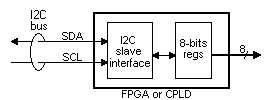
目标:通过I2C进行IO端口扩展,SCL在FPGA/CPLD中作为时钟信号
I2C从模块连接到一个小的8位存储器,这个存储器可以通过I2C总线进行读写,这8位为FPGA/CPLD的外部连线,这样就实现了一个I2C的IO端口扩展
第一步,先定义模块
module I2CslaveWith8bitsIO(SDA, SCL, IOout);
inout SDA;
input SCL;
output [7:0] IOout;
接着是我们需要的I2C“从”设备的7位地址
parameter I2C_ADR = 7'h27;
接着是“起始”和“终止”检测逻辑,这也是本设计中最神秘的部分。
// We use two wires with a combinatorial loop to detect the start and stop conditions
//  ... making sure these two wires don't get optimized away
wire SDA_shadow    /* synthesis keep = 1 */;
wire start_or_stop /* synthesis keep = 1 */;
assign SDA_shadow = (~SCL | start_or_stop) ? SDA : SDA_shadow;
assign start_or_stop = ~SCL ? 1'b0 : (SDA ^ SDA_shadow);

reg incycle;
always @(negedge SCL or posedge start_or_stop)
if(start_or_stop) incycle <= 1'b0; else if(~SDA) incycle <= 1'b1;
现在我们可以计数进来的I2C的位数。
reg [3:0] bitcnt;  // counts the I2C bits from 7 downto 0, plus an ACK bit
wire bit_DATA = ~bitcnt[3];  // the DATA bits are the first 8 bits sent
wire bit_ACK = bitcnt[3];  // the ACK bit is the 9th bit sent
reg data_phase;

always @(negedge SCL or negedge incycle)
if(~incycle)
begin
    bitcnt <= 4'h7;  // the bit 7 is received first
    data_phase <= 0;
end
else
begin
    if(bit_ACK)
    begin
    	bitcnt <= 4'h7;
    	data_phase <= 1;
    end
    else
    	bitcnt <= bitcnt - 4'h1;
end
并且检测I2C的地址是否匹配
wire adr_phase = ~data_phase;
reg adr_match, op_read, got_ACK;
// sample SDA on posedge since the I2C spec specifies as low as 0µs hold-time on negedge
reg SDAr;  always @(posedge SCL) SDAr<=SDA;
reg [7:0] mem;
wire op_write = ~op_read;

always @(negedge SCL or negedge incycle)
if(~incycle)
begin
    got_ACK <= 0;
    adr_match <= 1;
    op_read <= 0;
end
else
begin
    if(adr_phase & bitcnt==7 & SDAr!=I2C_ADR[6]) adr_match<=0;
    if(adr_phase & bitcnt==6 & SDAr!=I2C_ADR[5]) adr_match<=0;
    if(adr_phase & bitcnt==5 & SDAr!=I2C_ADR[4]) adr_match<=0;
    if(adr_phase & bitcnt==4 & SDAr!=I2C_ADR[3]) adr_match<=0;
    if(adr_phase & bitcnt==3 & SDAr!=I2C_ADR[2]) adr_match<=0;
    if(adr_phase & bitcnt==2 & SDAr!=I2C_ADR[1]) adr_match<=0;
    if(adr_phase & bitcnt==1 & SDAr!=I2C_ADR[0]) adr_match<=0;
    if(adr_phase & bitcnt==0) op_read <= SDAr;
    // we monitor the ACK to be able to free the bus when the master doesn't ACK during a read operation
    if(bit_ACK) got_ACK <= ~SDAr;

    if(adr_match & bit_DATA & data_phase & op_write) mem[bitcnt] <= SDAr;  // memory write
end
如有需要驱动=SDA信号线
wire mem_bit_low = ~mem[bitcnt[2:0]];
wire SDA_assert_low = adr_match & bit_DATA & data_phase & op_read & mem_bit_low & got_ACK;
wire SDA_assert_ACK = adr_match & bit_ACK & (adr_phase | op_write);
wire SDA_low = SDA_assert_low | SDA_assert_ACK;
assign SDA = SDA_low ? 1'b0 : 1'bz;

assign IOout = mem;
endmodule
结果如何?
此代码已经在Xilinx和Altera的多个器件上进行过测试,能够同硬化的I2C主进行通信,在这里可以下载完整的代码
不过此代码有两个缺点::
- 在FPGA/CPLD中SCL被用做了时钟信号,强烈建议在SCL输入端加入施密特触发器以避免错误的行为发生,如果不加施密特触发器,在SCL线上的任何噪声或振铃都会导致多余的时钟周期,导致功能失效
- “起始”和“终止”的条件检查逻辑采用的是组合反馈环路,这种方式是不建议的。同样其它电路的异步复位也不建议采用“周期内信号”
如果你能够容忍这些缺点,这应该是I2C从模式非常简洁的设计,否则你只能用外部时钟对SDA和SCL进行过取样,通过数字滤波器将毛刺给滤除掉,“起始”和“终止”的检测也变得比较容易,当然代价就是设计变得更复杂。
相关设计资源参考
- Philips多方面深度讨论I2C的应用指南
- 关于I2C和SMBus区别的文章(SMBus是由Intel公司开发的,基本跟I2C兼容)
- 苏老师公众号文章 - 几种最常用的串行数据传输总线(2)-I2C
- Lattice Semi的I2C Master使用说明,及IP参考代码下载
- Lattice Semi的支持Wisbone总线的I2C Master使用说明,及IP参考代码下载
- Lattice Semi的I2C总线控制器使用说明,及IP参考代码下载
- Lattice Semi的I2C主控制器使用说明,及IP参考代码下载
- Lattice Semi的用于嵌入式功能块中的I2C从设备使用说明,及IP参考代码下载
- Lattice Semi的I2C从到SPI主的桥接使用说明,及IP参考代码下载
- FPGA4FUN上的关于I2C的介绍及相应的Verilog代码资源
- FPGA4FUN上的I2C从设备的完整的代码
更多关于I2C等接口的资料和学习案例参见串行总线

