圆弧板边的设置
为了美观,或者设计者的要求会将板子设计成圆弧形的板边,这时候就要使用绘制圆弧这个工具了,
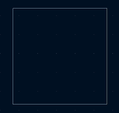
首先绘制一个矩形的板子如图所示,我们要在这个的基础上去绘制圆弧形的板边
绘制矩形板边
首先将层切换到Edge.Cuts层,然后我们可以在设计界面的右边看到一个半弧的标志,鼠标悬停上面我们可以看到显示绘制圆弧的字样如图所示:
选择板边层
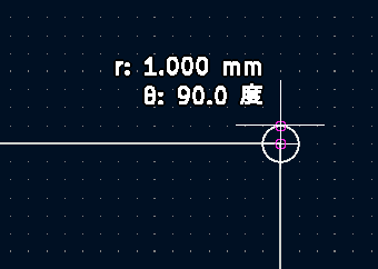
然后点击绘制半弧,点击板子的一个顶点,以这个点为中心绘制一个r为1mm,角度为90度的半弧如图所示:
绘制圆弧
然后将半弧进行移动旋转使半弧的两个端点与两边的线相切如图所示,
移动圆弧
圆弧的放置
删除之前的矩形之后,再用线将四边连接即可得到一个圆角矩形了。
圆角矩形
In this recipe, you will learn how to create a rounded corner, like the one in the example in Figure 33.1. In this example, the arrows point to some of the rounded corners of the board. Although it does take additional work to design these corners, they do contribute to making this board look and feel 'quality'.
Figure 33.1: The arrows point to some of the rounded corners on this board. To practice how to create an outer and an inner rounded corner, let’s use an empty page in Pcbnew. Start a new KiCad project, and open KiCad. Since we will be designing the layout of a PCB, opt for a large grid and zoom factor. In my design, I use 1.27 mm (50 mils) for the grid size, and 11.46 for the zoom factor. Select the Edge.Cuts layer, and click on the Line tool ( ). In Figure 33.2 you can see our objective: our aim is to replace the 90-degree angled of this board with rounded corners.
Figure 33.2: We will convert the angled corners into rounded corners. We will need to re-draw parts of this outline, but if you wish to follow along with the practice operations, go ahead and draw the polygon.
To create rounded shapes, you will use the arc tool ( ). Click on its button to select it. Next, zoom in to the top left corner to practice using the arc tool. To draw an arc, you will go through a sequence of three clicks. First, click on the location where you wish to set the centre of the circle of which the arc is part of. Then, click at a location that defines the radius of the arc. Finally, click to define the length of the arc. In Figure 33.3, you can see this sequence.
Figure 33.3: Creating an arc involves three clicks.
From left to right: 1. Using the grid as a guide, click inside the corner so that the centre of the arc’s circle is across the corner. I am using a 1.27 mm grid, so I placed my mouse pointer to the grid dot that is located 1.27 mm horizontally and 1.27 mm vertically from the corner.
- Move the mouse one grid segment upwards, to meet the existing outline line, and click. This defines the radius of the arc, which is 1.27 mm.
- Finally, draw the 90 degree arc itself. Move the mouse towards the vertical line until it is over the grid dot, 1.27 mm below the corner. Click to complete the process. In the fourth image of Figure 33.3 you can see the outcome of this process. This was only practice. The corner is still there, and to complete the work we will need to remove the lines that make it, leaving only the arc. But before we get to that, I’d like to show you one more thing.
Still working on the top left corner, create a new, longer arc, like the one in Figure 33.4 (the new arc is the longer one).
Figure 33.4: You can create arcs of arbitrary lengths.
To create this longe arc, place your mouse on the grid point that is 2 x 1.27 mm = 2.54 mm vertically and 2.54 mm horizontally away from the corner. Define the arc radius and draw the arc in the same way as the first arc. You
will end up with a longer arc than the first one. This is how you can create rounded corners of arbitrary size.
Let’s continue to finish work on this corner (delete the longer arc, if you created it). The next step is to remove the lines that create the 90-degree corner. This process is described visually in Figure 33.5.
Figure 33.5:Delete and replace the lines, leaving the rounded corner in place.
Refer to Figure 33.5. Start with the horizontal line. Place your mouse over it and type the Del key to remove the line (1). Use the line tool to restore the horizontal line, but this time start it from the top-right corner to the edge of the arc (2). With the grid size at 1.27 mm, it should not be a problem creating a perfectly closed outline. If the outline is not closed, KiCad will show a warning message when you attempt to use the 3D Viewer. Continue with deleting the vertical line (3). Restore this line, and you will end up with an outline like the one in Figure 33.6, with a rounded corner.
Figure 33.6:The top left corner is now rounded.
Follow the exact same process to replace the rest of the external corners with rounded corners. Each time, draw the arc in the size you want, and replace the straight lines, always taking care to produce a perfect closed outline (Figure 33.7).
Figure 33.7: All external corners are rounded; let's work on the internal corner next.
For the remaining corner, the internal corner, we’ll use a slightly modified process. Instead of placing the centre of the arc’s circle inside the outline, we’ll place it on the outside. The process is described visually in Figure 33.8.
Figure 33.8: Creating an internal corner.
Start by clicking on the grid dot that is 1.27 mm horizontally and 1.27 mm vertically away from the corner, outside the outline (1). Move the mouse pointer right, on the existing line, and click to define the radius (2). Then draw the arc so that it meets the horizontal line (3). Finally, delete the two straight lines that make up the corner, and replace them with new lines that meet the arc. In Figure 33.9 you can see the completed board outline with rounded corners.
Figure 33.9: The board outline with completed rounded corners.
As you learned in the chapter 'PCB layout process', you should design the outline of the board before you place any footprints on it and do any routing. This will make it much easier to draw the outline since you will not need to negotiate obstacles. This is also the best time to create screw holes and other openings (as, for example, for passing wires). Please read the 'Creating mounting holes and openings' recipe to learn more about this.
