交通灯控制系统项目总结报告
项目介绍
本次项目旨在构建一个交通灯控制系统,主要使用常规的 74 系列元器件,通过 WebIDE 的图形化编程以及 Verilog 语言编程实现多种功能。在硬件方面,涉及到数码管、蜂鸣器、接近传感器以及用于环境光感知的小脚丫核心板上的单色 LED 等元器件。软件编程上,图形化编程用于实现数码管计时信息显示和蜂鸣器报警功能,同时使用Diamond软件实现接近传感器检测人员走近以及环境光感知自动点亮路灯的功能。
项目设计思路
图形化编程思路
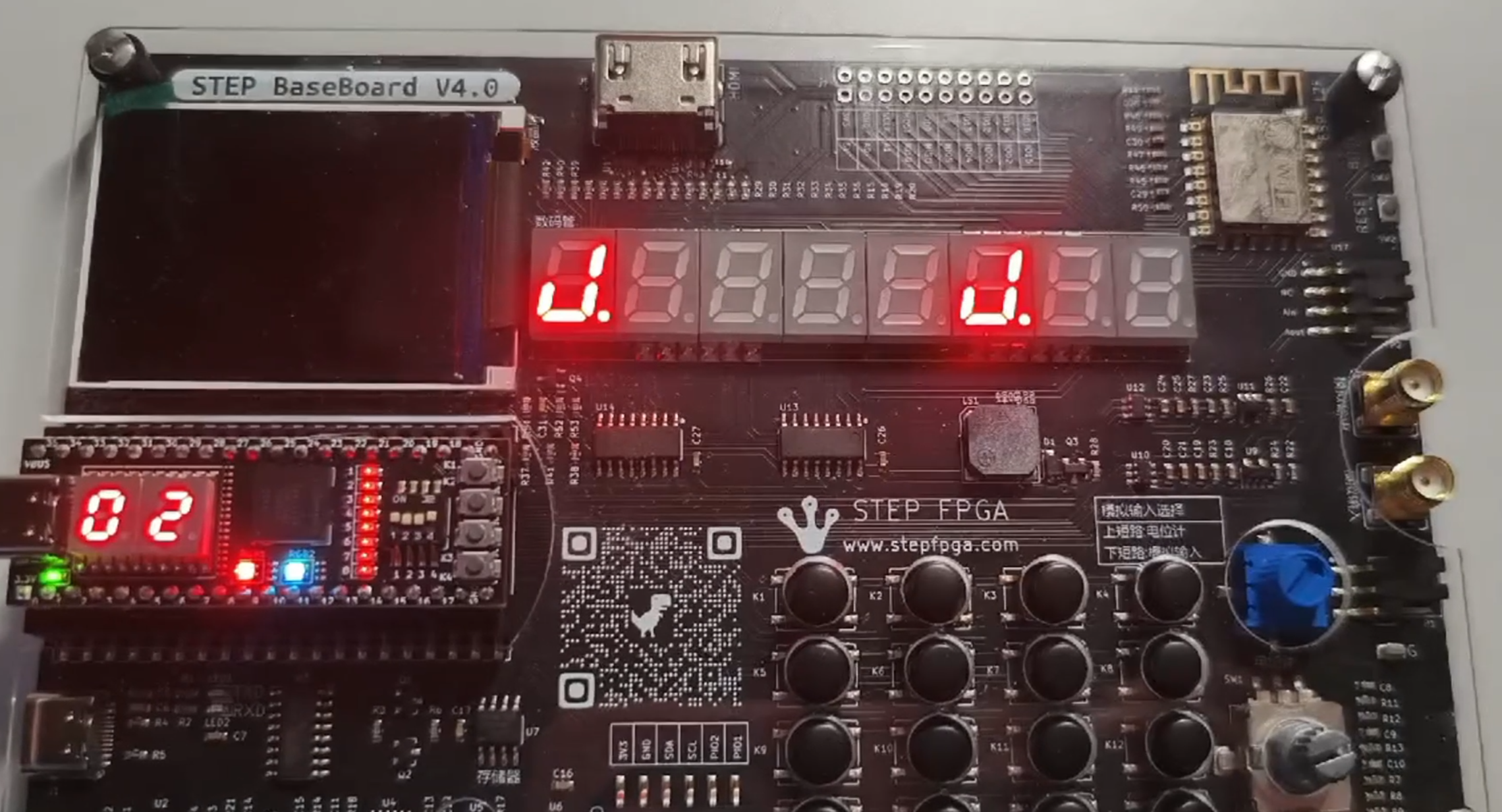
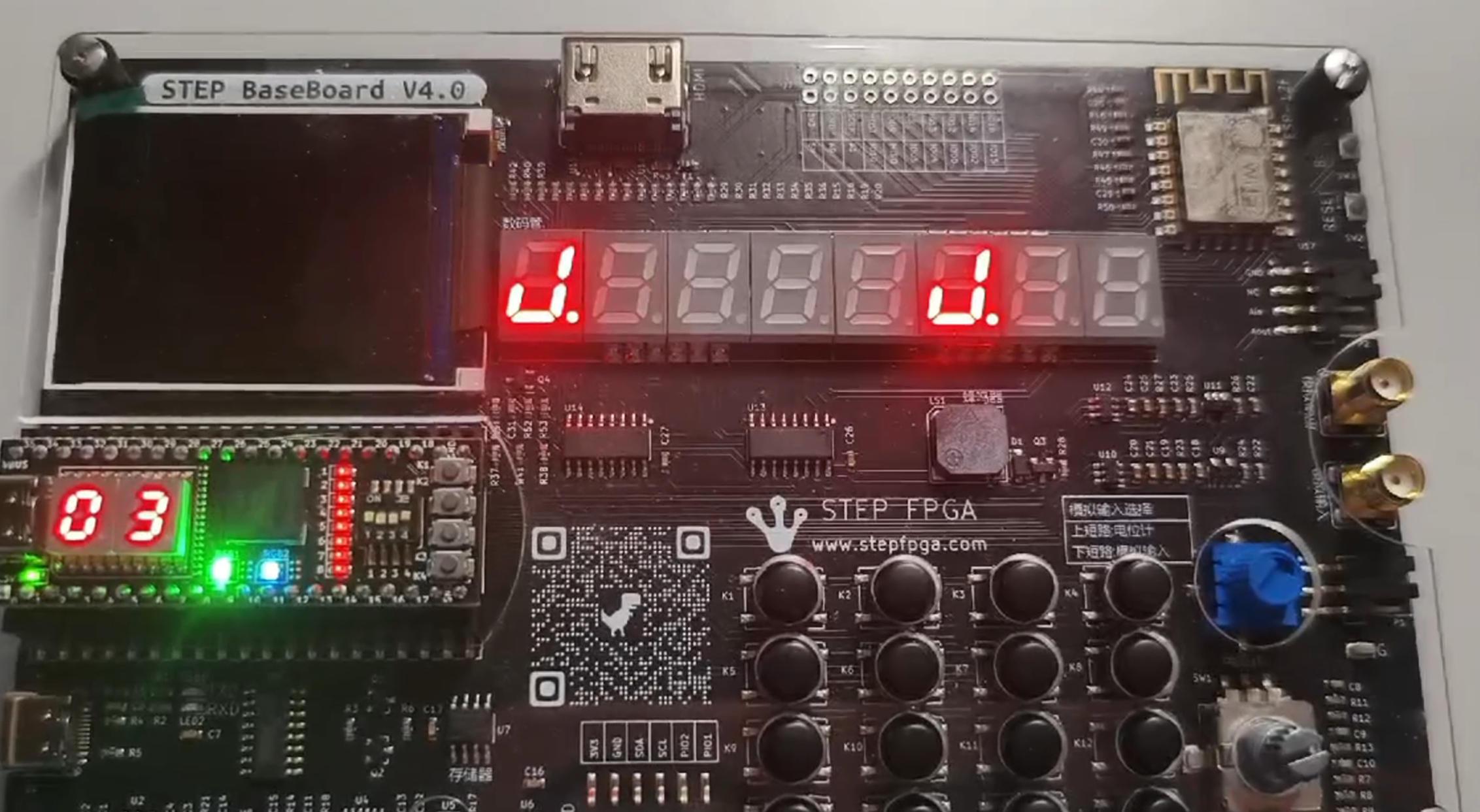
我们利用核心板上的rgb_led灯来模拟红绿灯,同时在核心板上的数码管上显示红绿灯的剩余时间,并让蜂鸣器在红绿灯切换时报警
Diamond编程思路
为了整个项目的完整性,我们将图形化编程的部分也整合到了Diamond项目中,当有物体靠近接近传感器时,蜂鸣器会报警,距离越近,音调越高,当有物体遮挡住传感器时,其检测到的亮度变暗,此时板上的led灯会亮起,亮度越暗,led灯亮起的数量越多。
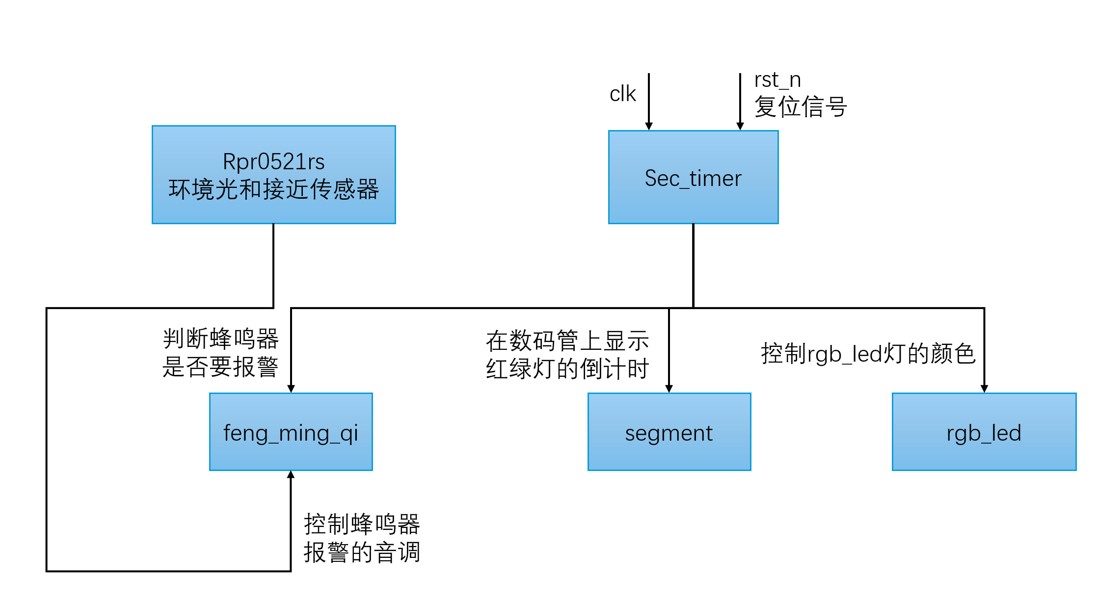
功能框图
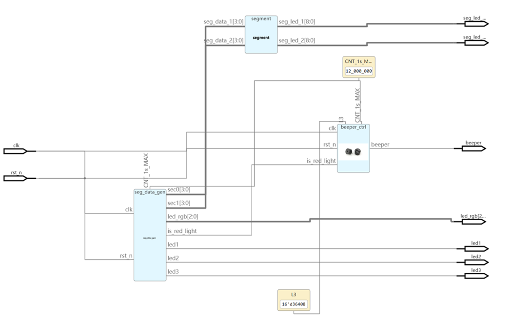
关键代码介绍
软件流程图
数码管显示模块
输入数据:模块接收两个 4 位输入信号 seg_data_1 和 seg_data_2,分别表示两个数码管需要显示的数字(0~9)。
译码表查表:通过 seg 数组,将输入的数字映射为对应的数码管驱动信号。
输出驱动信号:将查表得到的驱动信号输出到 seg_led_1 和 seg_led_2,用于驱动数码管显示对应的数字。
// Module Function:数码管的译码模块初始化


module segment (seg_data_1,seg_data_2,seg_led_1,seg_led_2);


       input [3:0] seg_data_1;        //数码管需要显示0~9十个数字,所以最少需要4位输入做译码

       input [3:0] seg_data_2;        //小脚丫上第二个数码管

       output [8:0] seg_led_1;        //在小脚丫上控制一个数码管需要9个信号 MSB~LSB=DIG、DP、G、F、E、D、C、B、A

       output [8:0] seg_led_2;        //在小脚丫上第二个数码管的控制信号  MSB~LSB=DIG、DP、G、F、E、D、C、B、A


    reg [8:0] seg [9:0];             //定义了一个reg型的数组变量,相当于一个10*9的存储器,

                                                        //存储器一共有10个数,每个数有9位宽


    initial                          //在过程块中只能给reg型变量赋值,

                                                        //Verilog中有两种过程块always和initial

                                //initial和always不同,其中语句只执行一次

       begin

              seg[0] = 9'h3f;         //对存储器中第一个数赋值9'b00_0011_1111,相当于共阴极接地,DP点变低不亮,7段显示数字  0

              seg[1] = 9'h06;         //7段显示数字  1

              seg[2] = 9'h5b;         //7段显示数字  2

              seg[3] = 9'h4f;         //7段显示数字  3

              seg[4] = 9'h66;         //7段显示数字  4

              seg[5] = 9'h6d;         //7段显示数字  5

              seg[6] = 9'h7d;         //7段显示数字  6

              seg[7] = 9'h07;         //7段显示数字  7

              seg[8] = 9'h7f;         //7段显示数字  8

              seg[9] = 9'h6f;         //7段显示数字  9

            end


       assign seg_led_1 = seg[seg_data_1];      //连续赋值,这样输入不同四位数,

       assign seg_led_2 = seg[seg_data_2];      //就能输出对于译码的9位输出


endmodule
红绿灯倒计时模块
时钟分频:使用 24 位计数器 counter 实现 1 秒的时钟周期。
倒计时逻辑:根据当前时间递减倒计时,并在倒计时结束时切换红绿灯状态。
红绿灯状态切换:通过 is_red_light_R 信号控制红绿灯的切换。
灯光控制:根据红绿灯状态输出对应的 RGB LED 颜色信号。
输出信号:将倒计时秒数和红绿灯状态通过输出信号提供给外部模块。
reg        light_red;        // 表示红灯状态(红灯时为1,绿灯时为0)

reg [23:0] counter;          // 用于12百万周期的24位计数器

reg [4:0] current_time;      // 当前的秒数计时器(最大31秒)


always @(posedge clk or negedge rst_n) begin

    if (!rst_n) begin

        counter <= 0;

        sec0_R <= GREEN_SEC0; sec1_R <= GREEN_SEC1;

        light_red <= 0;     // 初始输出绿灯

    end else if (counter == CNT_1s_MAX - 1) begin

        counter <= 0;  // 每秒重置计数器

        if (sec0_R == 0) begin

            if(sec1_R == 0)begin

                case(is_red_light_R)

                    1:begin

                        sec0_R <= RED_SEC0; sec1_R <= RED_SEC1;

                    end

                    default:begin

                        sec0_R <= GREEN_SEC0; sec1_R <= GREEN_SEC1;

                    end

                endcase

            end else begin

                sec1_R <= sec1_R - 1;  // 递减倒计时器

                sec0_R <= 9;

            end

        end else begin

            sec0_R <= sec0_R - 1;  // 递减倒计时器

        end

        light_red <= is_red_light_R;  // 输出当前红绿灯状态(红灯为1,绿灯为0)


    end else begin

        counter <= counter + 1;  // 递增计数器

    end

end

always@(posedge clk or negedge rst_n)begin

    if(!rst_n)

        is_red_light_R <= 0;

    else if(counter == CNT_1s_MAX - 2 && sec1_R == 0 && sec0_R == 0)

        // 当当前时间倒计时到0时,切换红绿灯状态

        is_red_light_R <= ~is_red_light_R;

    else

        is_red_light_R <= is_red_light_R;

end
蜂鸣器报警模块
周期性信号生成:通过计数器 cnt 生成周期性信号,用于控制蜂鸣器的报警频率。
蜂鸣器输出控制:根据蜂鸣器使能信号 beeper_en 和周期性信号 cnt 控制蜂鸣器的输出状态。
红绿灯状态检测:通过延迟信号 is_red_light_d1 检测红绿灯状态的变化。
蜂鸣器报警计时:通过计数器 cnt_2s 计时蜂鸣器报警的持续时间(2 秒)。
蜂鸣器使能控制:当红绿灯状态发生变化时,蜂鸣器使能信号 beeper_en 置为 1,蜂鸣器开始报警;当报警持续时间达到 2 秒时,蜂鸣器使能信号清零,蜂鸣器停止报警。
always @(posedge clk or negedge rst_n)

        if(!rst_n)

            cnt <= 1'b1;

        else if(cnt >= L3)

            cnt <= 1'b1;

        else

            cnt <= cnt + 1'b1;


    always@(posedge clk or negedge rst_n)

        if(!rst_n)

            beeper_R <= 1'b1;

        else if(beeper_en)

            if(cnt < L3 >>1)

                beeper_R <= 1'b1;

            else

                beeper_R <= 1'b0;

        else

            beeper_R <= beeper_R;


    always@(posedge clk or negedge rst_n)begin

        if(!rst_n)begin

            is_red_light_d1 <= is_red_light;

        end else begin

            is_red_light_d1 <= is_red_light;

        end

    end


    // 蜂鸣器响2s

    always@(posedge clk or negedge rst_n)begin

        if(!rst_n)

            cnt_2s <= 32'd0;

        else if(beeper_en)

            cnt_2s <= cnt_2s + 1'b1;

        else

            cnt_2s <= 32'd0;

    end


    //上升沿或者下降沿(红绿灯切换的2s时间内)蜂鸣器会工作

    always@(posedge clk or negedge rst_n)begin

        if(!rst_n)

            beeper_en <= 1'b0;

        else if(~is_red_light_d1 & is_red_light)

            beeper_en <= 1'b1;

        else if(is_red_light_d1 & ~is_red_light)

            beeper_en <= 1'b1;

        else if(cnt_2s == CNT_1s_MAX << 1)

            beeper_en <= 1'b0;

        else

            beeper_en <= beeper_en;

end
传感器驱动模块:
I2C通信: 使用I2C协议与RPR0521RS传感器通信。
传感器数据读取: 读取传感器的ALS(环境光传感器)、IR(红外)和Prox(接近传感器)数据。
数据有效脉冲: 提供一个数据有效脉冲dat_valid,用于指示数据读取完成。
状态机控制: 使用有限状态机(FSM)控制通信流程,包括初始化、写配置、读数据等。
always@(posedge clk_400khz or negedge rst_n) begin
if(!rst_n) begin //如果按键复位,将相关数据初始化
scl <= 1'd1; sda <= 1'd1; ack <= ACK; ack_flag <= 1'b0; cnt <= 1'b0;
cnt_main <= 1'b0; cnt_mode1 <= 1'b0; cnt_mode2 <= 1'b0;
cnt_start <= 1'b0; cnt_write <= 1'b0; cnt_read <= 1'b0; cnt_stop <= 1'b0;
cnt_delay <= 1'b0; num_delay <= 24'd4800;
state <= IDLE; state_back <= IDLE;
end else begin
case(state)
IDLE:begin //软件自复位,主要用于程序跑飞后的处理----------------0
scl <= 1'd1; sda <= 1'd1; ack <= ACK; ack_flag <= 1'b0; cnt <= 1'b0;
cnt_main <= 1'b0; cnt_mode1 <= 1'b0; cnt_mode2 <= 1'b0;
cnt_start <= 1'b0; cnt_write <= 1'b0; cnt_read <= 1'b0; cnt_stop <= 1'b0;
cnt_delay <= 1'b0; num_delay <= 24'd4800;
state <= MAIN; state_back <= IDLE;
end
MAIN:begin//-------------------------1
if(cnt_main >= 4'd11) cnt_main <= 4'd4; //写完控制指令后循环读数据
else cnt_main <= cnt_main + 1'b1;
case(cnt_main)
4'd0: begin dev_addr <= 7'h38; reg_addr <= 8'h40; reg_data <= 8'h0a; state <= MODE1; end //写入配置
4'd1: begin dev_addr <= 7'h38; reg_addr <= 8'h41; reg_data <= 8'hc6; state <= MODE1; end //写入配置
4'd2: begin dev_addr <= 7'h38; reg_addr <= 8'h42; reg_data <= 8'h02; state <= MODE1; end //写入配置
4'd3: begin dev_addr <= 7'h38; reg_addr <= 8'h43; reg_data <= 8'h01; state <= MODE1; end //写入配置
4'd4: begin state <= DELAY; dat_valid <= 1'b0; end //12ms延时
4'd5: begin dev_addr <= 7'h38; reg_addr <= 8'h44; state <= MODE2; end //读取配置
4'd6: begin prox_dat<= {dat_h,dat_l}; end //读取数据
4'd7: begin dev_addr <= 7'h38; reg_addr <= 8'h46; state <= MODE2; end //读取配置
4'd8: begin ch0_dat <= {dat_h,dat_l}; end //读取数据
4'd9: begin dev_addr <= 7'h38; reg_addr <= 8'h48; state <= MODE2; end //读取配置
4'd10: begin ch1_dat <= {dat_h,dat_l}; end //读取数据
4'd11: begin dat_valid <= 1'b1; end //读取数据
default: state <= IDLE; //如果程序失控,进入IDLE自复位状态
endcase
end
MODE1:begin //单次写操作------------------------2
if(cnt_mode1 >= 4'd5) cnt_mode1 <= 1'b0; //对START中的子状态执行控制cnt_start
else cnt_mode1 <= cnt_mode1 + 1'b1;
state_back <= MODE1;
case(cnt_mode1)
4'd0: begin state <= START; end //I2C通信时序中的START
4'd1: begin data_wr <= dev_addr<<1; state <= WRITE; end //设备地址
4'd2: begin data_wr <= reg_addr; state <= WRITE; end //寄存器地址
4'd3: begin data_wr <= reg_data; state <= WRITE; end //写入数据
4'd4: begin state <= STOP; end //I2C通信时序中的STOP
4'd5: begin state <= MAIN; end //返回MAIN
default: state <= IDLE; //如果程序失控,进入IDLE自复位状态
endcase
end
MODE2:begin //两次读操作----------------------3
if(cnt_mode2 >= 4'd10) cnt_mode2 <= 1'b0; //对START中的子状态执行控制cnt_start
else cnt_mode2 <= cnt_mode2 + 1'b1;
state_back <= MODE2;
case(cnt_mode2)
4'd0: begin state <= START; end //I2C通信时序中的START
4'd1: begin data_wr <= dev_addr<<1; state <= WRITE; end //设备地址
4'd2: begin data_wr <= reg_addr; state <= WRITE; end //寄存器地址
4'd3: begin state <= START; end //I2C通信时序中的START
4'd4: begin data_wr <= (dev_addr<<1)|8'h01; state <= WRITE; end //设备地址
4'd5: begin ack <= ACK; state <= READ; end //读寄存器数据
4'd6: begin dat_l <= data_r; end
4'd7: begin ack <= NACK; state <= READ; end //读寄存器数据
4'd8: begin dat_h <= data_r; end
4'd9: begin state <= STOP; end //I2C通信时序中的STOP
4'd10: begin state <= MAIN; end //返回MAIN
default: state <= IDLE; //如果程序失控,进入IDLE自复位状态
endcase
end
START:begin //I2C通信时序中的起始START------------------------4
if(cnt_start >= 3'd5) cnt_start <= 1'b0; //对START中的子状态执行控制cnt_start
else cnt_start <= cnt_start + 1'b1;
case(cnt_start)
3'd0: begin sda <= 1'b1; scl <= 1'b1; end //将SCL和SDA拉高,保持4.7us以上
3'd1: begin sda <= 1'b1; scl <= 1'b1; end //clk_400khz每个周期2.5us,需要两个周期
3'd2: begin sda <= 1'b0; end //SDA拉低到SCL拉低,保持4.0us以上
3'd3: begin sda <= 1'b0; end //clk_400khz每个周期2.5us,需要两个周期
3'd4: begin scl <= 1'b0; end //SCL拉低,保持4.7us以上
3'd5: begin scl <= 1'b0; state <= state_back; end //clk_400khz每个周期2.5us,需要两个周期,返回MAIN
default: state <= IDLE; //如果程序失控,进入IDLE自复位状态
endcase
end
WRITE:begin //I2C通信时序中的写操作WRITE和相应判断操作ACK-----------------------------5
if(cnt <= 3'd6) begin //共需要发送8bit的数据,这里控制循环的次数
if(cnt_write >= 3'd3) begin cnt_write <= 1'b0; cnt <= cnt + 1'b1; end
else begin cnt_write <= cnt_write + 1'b1; cnt <= cnt; end
end else begin
if(cnt_write >= 3'd7) begin cnt_write <= 1'b0; cnt <= 1'b0; end //两个变量都恢复初值
else begin cnt_write <= cnt_write + 1'b1; cnt <= cnt; end
end
case(cnt_write)
//按照I2C的时序传输数据
3'd0: begin scl <= 1'b0; sda <= data_wr[7-cnt]; end //SCL拉低,并控制SDA输出对应的位
3'd1: begin scl <= 1'b1; end //SCL拉高,保持4.0us以上
3'd2: begin scl <= 1'b1; end //clk_400khz每个周期2.5us,需要两个周期
3'd3: begin scl <= 1'b0; end //SCL拉低,准备发送下1bit的数据
//获取从设备的响应信号并判断
3'd4: begin sda <= 1'bz; end //释放SDA线,准备接收从设备的响应信号
3'd5: begin scl <= 1'b1; end //SCL拉高,保持4.0us以上
3'd6: begin ack_flag <= i2c_sda; end //获取从设备的响应信号并判断
3'd7: begin scl <= 1'b0; if(ack_flag)state <= state; else state <= state_back; end //SCL拉低,如果不应答循环写
default: state <= IDLE; //如果程序失控,进入IDLE自复位状态
endcase
end
READ:begin //I2C通信时序中的读操作READ和返回ACK的操作----------------------------6
if(cnt <= 3'd6) begin //共需要接收8bit的数据,这里控制循环的次数
if(cnt_read >= 3'd3) begin cnt_read <= 1'b0; cnt <= cnt + 1'b1; end
else begin cnt_read <= cnt_read + 1'b1; cnt <= cnt; end
end else begin
if(cnt_read >= 3'd7) begin cnt_read <= 1'b0; cnt <= 1'b0; end //两个变量都恢复初值
else begin cnt_read <= cnt_read + 1'b1; cnt <= cnt; end
end
case(cnt_read)
//按照I2C的时序接收数据
3'd0: begin scl <= 1'b0; sda <= 1'bz; end //SCL拉低,释放SDA线,准备接收从设备数据
3'd1: begin scl <= 1'b1; end //SCL拉高,保持4.0us以上
3'd2: begin data_r[7-cnt] <= i2c_sda; end //读取从设备返回的数据
3'd3: begin scl <= 1'b0; end //SCL拉低,准备接收下1bit的数据
//向从设备发送响应信号
3'd4: begin sda <= ack; end //发送响应信号,将前面接收的数据锁存
3'd5: begin scl <= 1'b1; end //SCL拉高,保持4.0us以上
3'd6: begin scl <= 1'b1; end //SCL拉高,保持4.0us以上
3'd7: begin scl <= 1'b0; state <= state_back; end //SCL拉低,返回MAIN状态
default: state <= IDLE; //如果程序失控,进入IDLE自复位状态
endcase
end
STOP:begin //I2C通信时序中的结束STOP-----------------------------7
if(cnt_stop >= 3'd5) cnt_stop <= 1'b0; //对STOP中的子状态执行控制cnt_stop
else cnt_stop <= cnt_stop + 1'b1;
case(cnt_stop)
3'd0: begin sda <= 1'b0; end //SDA拉低,准备STOP
3'd1: begin sda <= 1'b0; end //SDA拉低,准备STOP
3'd2: begin scl <= 1'b1; end //SCL提前SDA拉高4.0us
3'd3: begin scl <= 1'b1; end //SCL提前SDA拉高4.0us
3'd4: begin sda <= 1'b1; end //SDA拉高
3'd5: begin sda <= 1'b1; state <= state_back; end //完成STOP操作,返回MAIN状态
default: state <= IDLE; //如果程序失控,进入IDLE自复位状态
endcase
end
DELAY:begin //12ms延时---------------------------8
if(cnt_delay >= num_delay) begin
cnt_delay <= 1'b0;
state <= MAIN;
end else cnt_delay <= cnt_delay + 1'b1;
end
default:;
endcase
end
end
蜂鸣器报警模块
根据物体离传感器的距离控制蜂鸣器的音调
always@(posedge clk or negedge rst_n) begin

        if(!rst_n)begin

            cycle <= L3;

        end else begin

            if(prox_dat2 <= 30) begin cycle <= L3;end      //L1,

            else if(prox_dat2 >  30 && prox_dat2 <=  42) begin cycle <= L2;end    //L2,

            else if(prox_dat2 >  42 && prox_dat2 <=  54) begin cycle <= L3;end    //L3,

            else if(prox_dat2 >  54 && prox_dat2 <=  66) begin cycle <= L4;end    //L4,

            else if(prox_dat2 >  66 && prox_dat2 <=  78) begin cycle <= L5;end    //L5,

            else if(prox_dat2 >  78 && prox_dat2 <=  90) begin cycle <= L6;end    //L6,

            else if(prox_dat2 >  90 && prox_dat2 <= 102) begin cycle <= L7;end    //L7,

            else if(prox_dat2 > 102 && prox_dat2 <= 114) begin cycle <= M1;end    //M1,

            else if(prox_dat2 > 114 && prox_dat2 <= 126) begin cycle <= M2;end    //M2,

            else if(prox_dat2 > 126 && prox_dat2 <= 138) begin cycle <= M3;end    //M3,

            else if(prox_dat2 > 138 && prox_dat2 <= 150) begin cycle <= M4;end    //M4,

            else if(prox_dat2 > 150 && prox_dat2 <= 162) begin cycle <= M5;end    //M5,

            else if(prox_dat2 > 162 && prox_dat2 <= 174) begin cycle <= M6;end    //M6,

            else if(prox_dat2 > 174 && prox_dat2 <= 186) begin cycle <= M7;end    //M7,

            else if(prox_dat2 > 186 && prox_dat2 <= 198) begin cycle <= H1;end    //H1,

            else begin cycle <= H2;end    //H2,

        end

end
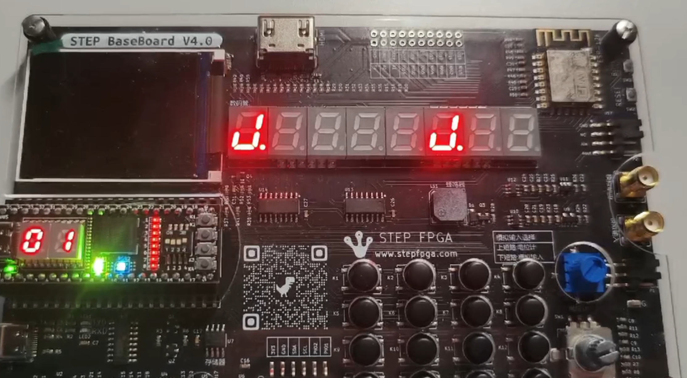
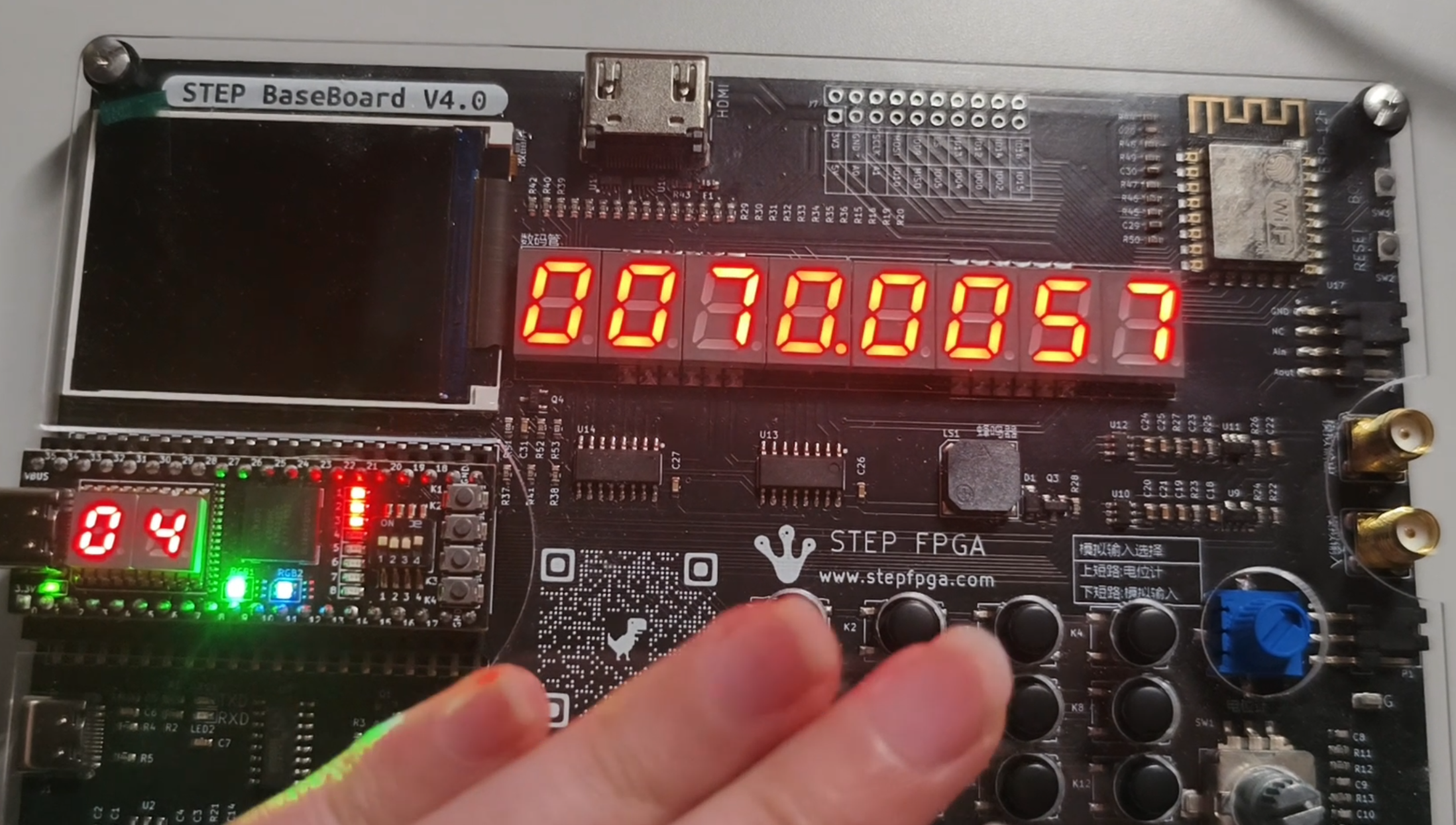
实物功能展示图
难题及解决办法
项目中涉及到大量 Verilog 编程,由于不熟悉 Verilog 语法和逻辑,导致难以读懂代码,无法进行有效的调试和修改。
解决方法:
学习 Verilog 基础知识:通过查阅 Verilog 教程、书籍和在线资源,学习 Verilog 的基本语法和常用模块结构。
分析模块功能:将代码分解为多个模块,逐个分析每个模块的功能和输入输出关系,理解其在系统中的作用。
使用仿真工具:利用仿真工具对 Verilog 代码进行仿真,观察信号波形和模块内部状态的变化,帮助理解代码的执行过程和功能实现。
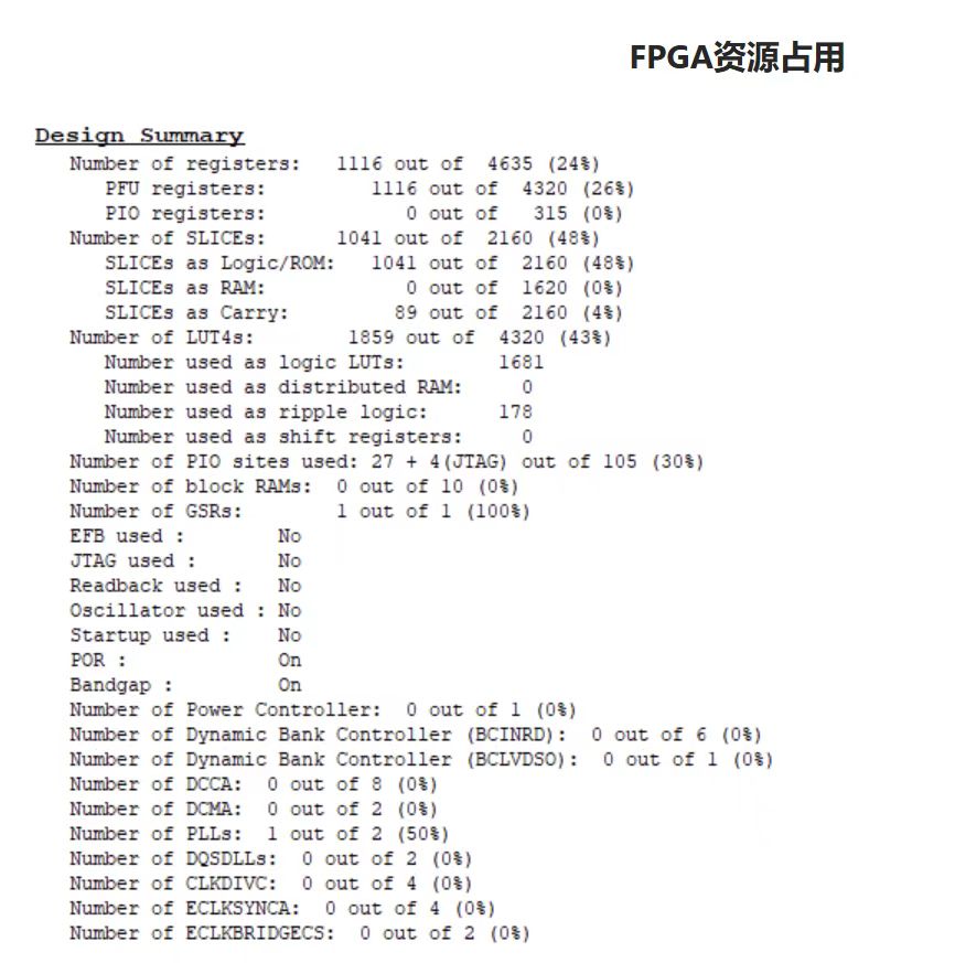
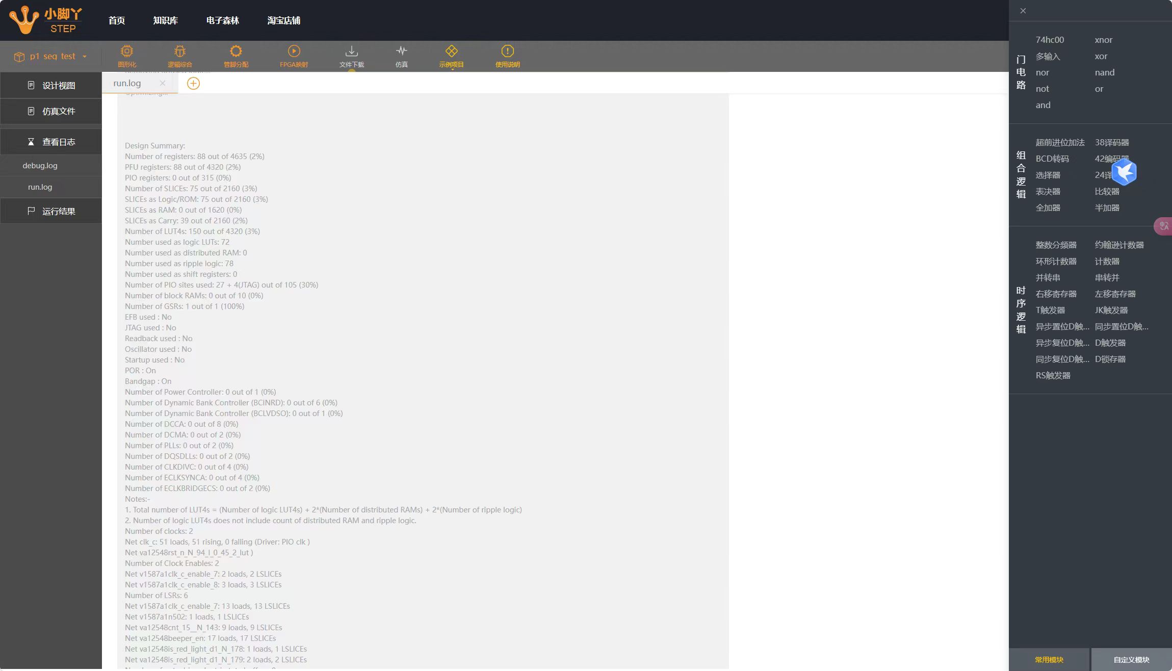
资源占用报告
心得体会
通过本次交通灯控制系统的项目实践,我收获颇丰。在项目实施过程中,遇到了不少难题,但通过查阅资料、请教老师和同学以及自己的不断尝试和探索,最终都得到了解决。这让我深刻体会到,在面对复杂的技术问题时,要有坚持不懈的精神和勇于尝试的态度,同时也要善于利用各种资源和工具,不断学习和积累经验。
总体而言,本次交通灯控制系统项目是一次非常宝贵的学习和实践经历,让我在硬件电路设计、软件编程以及问题解决等方面都得到了很大的提升,也为我今后的学习和工作积累了宝贵的经验。

