内容介绍
内容介绍
项目介绍
本项目旨在开发一个基于语音控制的计算器系统,通过大语言模型实现语音识别和命令生成。系统由PC端调用百度智能云进行语音合成、识别,FPGA计算器逻辑实现模块以及TFTLCD显示模块组成。用户通过键入文本调用百度智能云合成语音,然后用百度智能云识别合成的语音,系统将语音转换为计算命令,通过USB传输到FPGA扩展板,由FPGA执行计算操作,并在TFTLCD屏幕上显示计算过程和结果。
该项目充分利用了大模型的自然语言处理能力,结合FPGA的高效并行计算特性,实现了一个交互友好、功能完善的语音控制计算器。项目使用STEP Baseboard4.0底板和STEP MXO2 LPC核心板作为硬件平台,展示了软硬件协同设计的应用实例。
硬件介绍
本项目使用的硬件平台包括:
- STEP Baseboard4.0底板:
- 提供丰富的外设接口和扩展功能
- 集成USB通信接口,用于PC与FPGA之间的数据传输
- 配备TFTLCD显示屏接口,用于显示计算过程和结果
- 提供稳定的电源供应和系统时钟
- STEP MXO2 LPC核心板:
- 基于Lattice MXO2系列FPGA
- 提供足够的逻辑资源实现计算器功能
- 低功耗设计,适合嵌入式应用
- 支持多种I/O标准,便于与外部设备通信
- TFTLCD显示屏:
- 分辨率适中,能清晰显示计算过程和结果
- 与FPGA通过专用接口连接,支持高速数据传输
- 提供良好的视觉反馈,增强用户体验
- PC端设备:
- 调用百度智能云api合成语音
- 调用百度智能云api识别语音
- 通过USB接口与FPGA通信
流程图和项目设计思路
方案框图
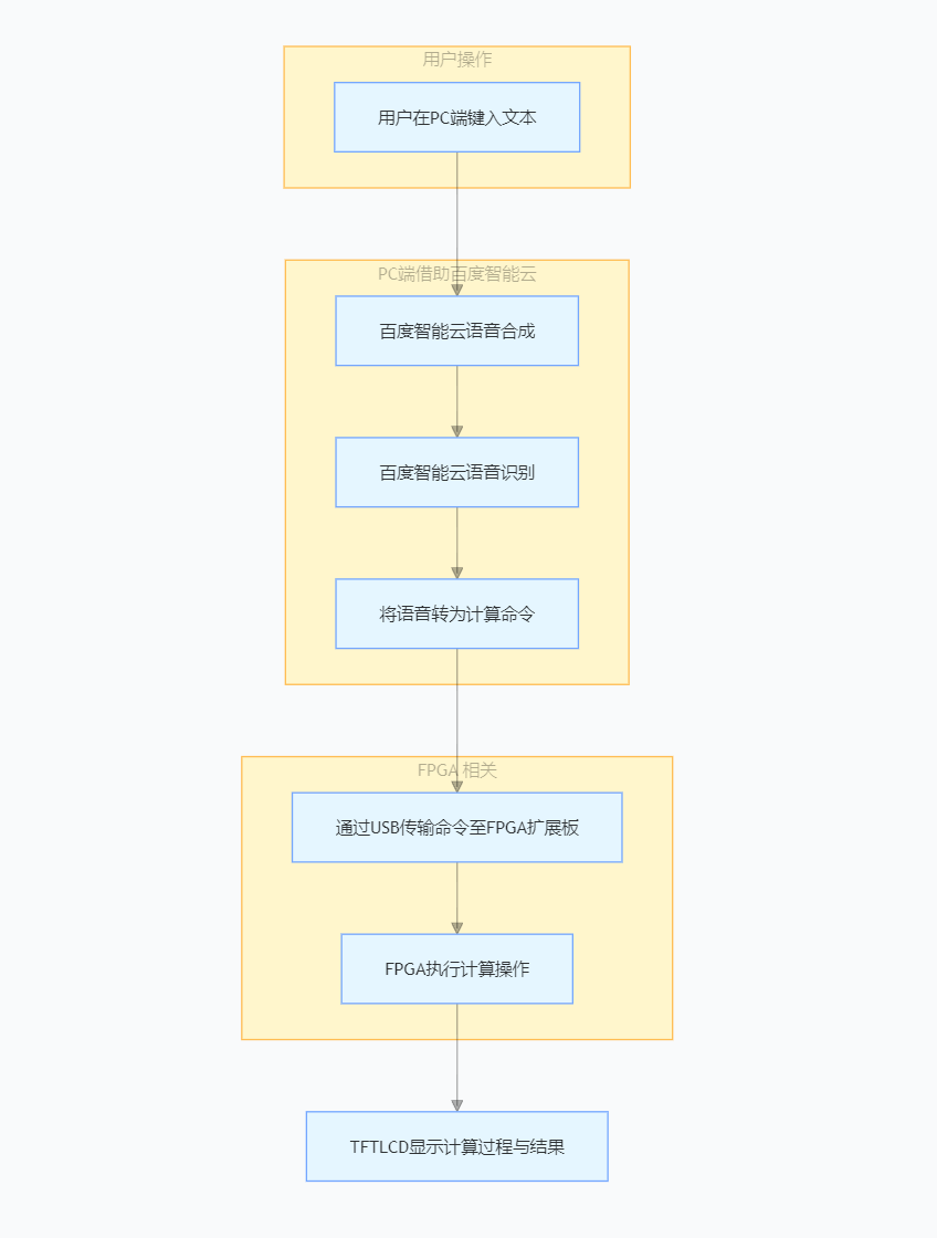
软件流程图
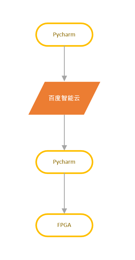
设计思路
- PC端语音处理:
- 利用百度智能云进行语音合成与识别
- 将识别出来的算式转换为标准化的计算命令
- 通过USB接口将命令发送至FPGA
- FPGA计算器实现:
- 接收并解析来自PC的计算命令
- 使用状态机实现计算器逻辑
- 支持基本算术运算(加、减、乘、除)
- 显示控制:
- FPGA驱动TFTLCD显示屏
功能展示图及关键代码
语音合成、转化、识别、发送
语音合成
import re
from aip import AipSpeech

# 百度智能云平台语音技能密钥
APP_ID = 'xxx'
API_KEY = 'xxx'
SECRET_KEY = 'xxx'

client = AipSpeech(APP_ID, API_KEY, SECRET_KEY)

# 自定义文本内容
text = "3加5"

# 语音合成
result = client.synthesis(text, 'zh', 1, {
    'vol': 8,  # 音量,取值 0-15,默认为 5 中音量
    'spd': 5,  # 语速,取值 0-9,默认为 5 中语速
    'pit': 5,  # 音调,取值 0-9,默认为 5 中语调
    'per': 0   # 发音人选择,0 为女声,1 为男声,3 为情感合成 - 度逍遥,4 为情感合成 - 度丫丫
})

# 检查返回结果是否为错误信息
wav_file = f"{text}.wav"
pcm_file = f"{text}.pcm"

# 检查返回结果是否为错误信息
if not isinstance(result, dict):
        # 保存合成的语音为 PCM 文件
        with open(pcm_file, 'wb') as f:
            f.write(result)
        print(f"已成功生成PCM 文件: {pcm_file}")

        # 保存合成的语音为 WAV 文件
        with open(wav_file, 'wb') as f:
            f.write(result)
        print(f"已成功生成WAV 文件: {wav_file}")
else:
        print("语音合成失败,错误信息:", result)
语音转化
from pydub import AudioSegment
from pydub.utils import which

ffmpeg_path = which("ffmpeg")
if ffmpeg_path is None:
    print("未找到 ffmpeg,请检查安装和环境变量配置。")
else:
    AudioSegment.converter = ffmpeg_path

    # 后续代码保持不变
    # 假设原始 PCM 文件采样率为 16000 Hz,声道数为 1,采样宽度为 2 字节(16 位)
    # 加载音频文件
    audio = AudioSegment.from_file(
        r"E:\pycharm\myprojects\audio_recog\3加5.pcm",
        format="pcm",
        frame_rate=16000,
        channels=1,
        sample_width=2
    )

    # 转换音频参数
    audio = audio.set_frame_rate(16000)
    audio = audio.set_channels(1)
    audio = audio.set_sample_width(2)  # 16 位 = 2 字节

    # 保存为 PCM 格式
    audio.export("output.pcm", format="s16le", codec="pcm_s16le")
语音识别
from aip import AipSpeech
import requests

# 替换为你的实际凭证
BaiduAPP_ID = 'xxx'
BaiduAPI_KEY = 'xxx'
SECRET_KEY = 'xxx'

client = AipSpeech(BaiduAPP_ID, BaiduAPI_KEY, SECRET_KEY)
def recognize_local_audio(file_path):
    try:
        with open(file_path, 'rb') as f:
            audio_data = f.read()
        result = client.asr(audio_data, 'pcm', 16000, {
            'dev_pid': 1537
        })
        print(result)
        if 'result' in result:
            return result['result'][0]
        else:
            return '语音未识别'
    except FileNotFoundError:
        print(f"错误:未找到文件 {file_path}")
        return '文件未找到,无法识别'
    except requests.exceptions.RequestException:
        print("错误:网络请求异常,请检查网络连接。")
        return '网络异常,无法识别'
    except Exception as e:
        print(f"发生未知错误: {e}")
        return '发生未知错误,无法识别'

if __name__ == '__main__':
    # 请替换为你的 PCM 文件路径
    audio_file_path = r"E:\pycharm\myprojects\audio_recog\output.pcm"


    recognition_result = recognize_local_audio(audio_file_path)
    print("识别结果:", recognition_result)
识别后发送命令
import serial
import time


def send_calculation(ser, num1, operator, num2):
    """发送一个完整的计算命令"""
    # 发送第一个操作数
    ser.write(bytes([ord('0') + num1]))
    print(f"发送操作数1: {num1}")
    time.sleep(0.1)

    # 发送操作符
    ser.write(bytes([ord(operator)]))
    print(f"发送操作符: {operator}")
    time.sleep(0.1)

    # 发送第二个操作数
    ser.write(bytes([ord('0') + num2]))
    print(f"发送操作数2: {num2}")
    time.sleep(0.1)


def main():
    port = 'COM3'  # 请修改为您实际使用的COM端口
    baud_rate = 9600

    try:
        ser = serial.Serial(
            port=port,
            baudrate=baud_rate,
            bytesize=serial.EIGHTBITS,
            parity=serial.PARITY_NONE,
            stopbits=serial.STOPBITS_ONE,
            timeout=1
        )
        print(f"成功打开串口 {port}")

        # 发送计算命令示例: 7+3
        send_calculation(ser, 7, '+', 3)

        # 延时后发送另一个计算命令: 9-5
        time.sleep(1)
        send_calculation(ser, 9, '-', 5)

        # 延时后发送乘法命令: 4*2
        time.sleep(1)
        send_calculation(ser, 4, '*', 2)

        # 延时后发送除法命令: 8/2
        time.sleep(1)
        send_calculation(ser, 8, '/', 2)

        # 关闭串口
        ser.close()
        print("串口已关闭")

    except serial.SerialException as e:
        print(f"串口错误: {e}")


if __name__ == "__main__":
    main()
uart
module uart_rx (
    input wire clk,                // 系统时钟
    input wire rst_n,              // 异步复位(低电平有效)
    input wire rx,                 // UART接收信号
    output reg [7:0] data,         // 接收到的数据字节
    output reg data_valid          // 数据有效指示
);
    // UART接收参数
    parameter BAUD_RATE = 9600;    // 波特率
    parameter CLOCK_FREQ = 50000000; // 系统时钟频率 50MHz
    localparam BIT_PERIOD = CLOCK_FREQ / BAUD_RATE;
    localparam HALF_BIT = BIT_PERIOD >> 1; // 半个位周期

    // 状态定义 - 使用参数化状态
    localparam IDLE = 2'd0;        // 空闲状态
    localparam START_BIT = 2'd1;   // 接收起始位
    localparam DATA_BITS = 2'd2;   // 接收数据位
    localparam STOP_BIT = 2'd3;    // 接收停止位

    // 寄存器定义
    reg [1:0] state;               // 当前状态 - 改为2位以支持更多状态
    reg [3:0] bit_count;           // 位计数器
    reg [7:0] rx_data;             // 数据接收缓冲区
    reg [15:0] clk_count;          // 时钟计数器
    reg rx_d1, rx_d2;              // 输入同步和去抖动

    // 超时检测
    reg [19:0] timeout_count;
    localparam TIMEOUT_VALUE = CLOCK_FREQ / 1000; // 1ms超时

    always @(posedge clk or negedge rst_n) begin
        if (!rst_n) begin
            state <= IDLE;
            bit_count <= 0;
            rx_data <= 0;
            clk_count <= 0;
            data <= 0;
            data_valid <= 0;
            rx_d1 <= 1'b1;
            rx_d2 <= 1'b1;
            timeout_count <= 0;
        end else begin
            // 输入同步和去抖动
            rx_d1 <= rx;
            rx_d2 <= rx_d1;

            // 默认清除数据有效标志
            data_valid <= 1'b0;

            // 超时处理
            if (state != IDLE) begin
                if (timeout_count >= TIMEOUT_VALUE) begin
                    state <= IDLE;
                    timeout_count <= 0;
                end else begin
                    timeout_count <= timeout_count + 1'b1;
                end
            end else begin
                timeout_count <= 0;
            end

            case (state)
                IDLE: begin
                    // 检测起始位的下降沿
                    if (rx_d2 == 1'b1 && rx_d1 == 1'b0) begin
                        state <= START_BIT;
                        clk_count <= 0;
                    end
                end

                START_BIT: begin
                    // 在起始位中间采样,确认是有效的起始位
                    if (clk_count == HALF_BIT) begin
                        if (rx_d1 == 1'b0) begin  // 确认起始位有效
                            state <= DATA_BITS;
                            bit_count <= 0;
                            clk_count <= 0;
                        end else begin
                            state <= IDLE;  // 无效起始位,返回空闲状态
                        end
                    end else begin
                        clk_count <= clk_count + 1'b1;
                    end
                end

                DATA_BITS: begin
                    if (clk_count == BIT_PERIOD) begin
                        clk_count <= 0;
                        // 在每个位中间采样
                        rx_data <= {rx_d1, rx_data[7:1]};  // LSB优先接收

                        if (bit_count == 7) begin  // 接收完8个数据位
                            state <= STOP_BIT;
                        end else begin
                            bit_count <= bit_count + 1'b1;
                        end
                    end else begin
                        clk_count <= clk_count + 1'b1;
                    end
                end

                STOP_BIT: begin
                    if (clk_count == BIT_PERIOD) begin
                        if (rx_d1 == 1'b1) begin  // 验证停止位
                            data <= rx_data;      // 输出接收到的数据
                            data_valid <= 1'b1;   // 设置数据有效标志
                        end
                        state <= IDLE;            // 返回空闲状态
                        clk_count <= 0;
                    end else begin
                        clk_count <= clk_count + 1'b1;
                    end
                end
            endcase
        end
    end
endmodule
解析命令
module command_parser (
    input wire clk,
    input wire rst_n,
    input wire [7:0] rx_data,
    input wire rx_valid,
    output reg [7:0] operand1,
    output reg [7:0] operand2,
    output reg [7:0] operator,
    output reg cmd_valid,
    output reg [1:0] state_debug  // 用于调试的状态输出
);
    // 状态定义
    localparam WAIT_OP1 = 2'b00;
    localparam WAIT_OPERATOR = 2'b01;
    localparam WAIT_OP2 = 2'b10;

    // 状态机内部状态
    reg [1:0] state;

    always @(posedge clk or negedge rst_n) begin
        if (!rst_n) begin
            state <= WAIT_OP1;
            cmd_valid <= 0;
            operand1 <= 0;
            operand2 <= 0;
            operator <= 0;
            state_debug <= 0;
        end else begin
            // 默认每个时钟周期清除命令有效标志
            cmd_valid <= 0;

            case (state)
                WAIT_OP1: begin
                    if (rx_valid) begin
                        if (rx_data >= 8'd48 && rx_data <= 8'd57) begin  // ASCII '0'-'9'
                            operand1 <= rx_data - 8'd48;  // 转换为数值
                            state <= WAIT_OPERATOR;
                        end
                    end
                end

                WAIT_OPERATOR: begin
                    if (rx_valid) begin
                        operator <= rx_data;  // 保存运算符的ASCII码
                        state <= WAIT_OP2;
                    end
                end

                WAIT_OP2: begin
                    if (rx_valid) begin
                        if (rx_data >= 8'd48 && rx_data <= 8'd57) begin  // ASCII '0'-'9'
                            operand2 <= rx_data - 8'd48;  // 转换为数值
                            cmd_valid <= 1;  // 设置命令有效标志
                            state <= WAIT_OP1;  // 返回初始状态,准备接收下一条命令
                        end
                    end
                end

                default: state <= WAIT_OP1;
            endcase

            state_debug <= state;  // 输出当前状态,便于调试
        end
    end
endmodule
计算逻辑
module calculator (
    input wire clk,
    input wire rst_n,
    input wire [7:0] operand1,
    input wire [7:0] operand2,
    input wire [7:0] operator,   // 使用8位来表示ASCII运算符
    input wire start_calc,
    output reg [7:0] result,
    output reg calc_done
);
    // ASCII运算符常量定义
    localparam ASCII_ADD = 8'd43; // '+'的ASCII码
    localparam ASCII_SUB = 8'd45; // '-'的ASCII码
    localparam ASCII_MUL = 8'd42; // '*'的ASCII码
    localparam ASCII_DIV = 8'd47; // '/'的ASCII码

    always @(posedge clk or negedge rst_n) begin
        if (!rst_n) begin
            result <= 0;
            calc_done <= 0;
        end else if (start_calc) begin
            case (operator)
                ASCII_ADD: result <= operand1 + operand2;           // 加法运算
                ASCII_SUB: result <= (operand1 >= operand2) ?       // 减法运算(防止下溢)
                                     (operand1 - operand2) : 8'd0;
                ASCII_MUL: result <= operand1 * operand2;           // 乘法运算(取低8位)
                ASCII_DIV: result <= (operand2 != 0) ?              // 除法运算(处理除零)
                                     (operand1 / operand2) : 8'd0;
                default: result <= 8'd0;                            // 未知操作符,结果置0
            endcase
            calc_done <= 1;
        end else begin
            calc_done <= 0;  // 复位完成标志,等待下一次计算
        end
    end
endmodule
TFTLCD显示
module show_string_number_ctrl
(
    input       wire            sys_clk             ,
    input       wire            sys_rst_n           ,
    input       wire            init_done           ,
    input       wire            show_char_done      ,
    // 添加三个输入:两个操作数和一个结果
    input       wire    [3:0]   num1                , // 第一个数字 (0-9)
    input       wire    [3:0]   num2                , // 第二个数字 (0-9)
    input       wire    [3:0]   result              , // 运算结果 (0-9)
    input       wire    [1:0]   op_sel              , // 运算符选择: 00-加, 01-减, 10-乘, 11-除

    output      wire            en_size             ,
    output      reg             show_char_flag      ,
    output      reg     [6:0]   ascii_num           ,
    output      reg     [8:0]   start_x             ,
    output      reg     [8:0]   start_y
);
//****************** Parameter and Internal Signal *******************//
reg     [1:0]   cnt1;


//最多显示2^5=32个字符
reg     [4:0]   cnt_ascii_num;


//显示总字符数量
parameter   CHAR_NUM    =   6;


// 将数字转换为ASCII码偏移值的参数(ASCII - 32)
parameter   ASCII_0     =   16'd16;  // '0' ASCII值48-32=16
parameter   ASCII_PLUS  =   16'd11;  // '+' ASCII值43-32=11
parameter   ASCII_MINUS =   16'd13;  // '-' ASCII值45-32=13
parameter   ASCII_MULT  =   16'd10;  // '*' ASCII值42-32=10
parameter   ASCII_DIV   =   16'd15;  // '/' ASCII值47-32=15
parameter   ASCII_EQUAL =   16'd29;  // '=' ASCII值61-32=29


//******************************* Main Code **************************//
//en_size为1时调用字体大小为16x8,为0时调用字体大小为12x6
assign  en_size = 1'b0;


always@(posedge sys_clk or negedge sys_rst_n)
    if(!sys_rst_n)
        cnt1 <= 'd0;
    else if(show_char_flag)
        cnt1 <= 'd0;
    else if(init_done && cnt1 < 'd3)
        cnt1 <= cnt1 + 1'b1;
    else
        cnt1 <= cnt1;

always@(posedge sys_clk or negedge sys_rst_n)
    if(!sys_rst_n)
        show_char_flag <= 1'b0;
    else if(cnt1 == 'd2)
        show_char_flag <= 1'b1;
    else
        show_char_flag <= 1'b0;


always@(posedge sys_clk or negedge sys_rst_n)
    if(!sys_rst_n)
        cnt_ascii_num <= 'd0;
    else if(cnt_ascii_num == CHAR_NUM)
        cnt_ascii_num <= 'd0;
    else if(init_done && show_char_done)
        cnt_ascii_num <= cnt_ascii_num + 1'b1;
    else
        cnt_ascii_num <= cnt_ascii_num;


always@(posedge sys_clk or negedge sys_rst_n)
    if(!sys_rst_n)
        ascii_num <= 'd0;
    else if(init_done)
        case(cnt_ascii_num)
            0 : ascii_num <= num1 + ASCII_0;  // 第一个数字
            1 : case(op_sel)
                    2'b00: ascii_num <= ASCII_PLUS;  // '+'
                    2'b01: ascii_num <= ASCII_MINUS; // '-'
                    2'b10: ascii_num <= ASCII_MULT;  // '*'
                    2'b11: ascii_num <= ASCII_DIV;   // '/'
                endcase
            2 : ascii_num <= num2 + ASCII_0;  // 第二个数字
            3 : ascii_num <= ASCII_EQUAL;     // '='
            4 : ascii_num <= result + ASCII_0;// 运算结果
            default: ascii_num <= 'd0;
        endcase


always@(posedge sys_clk or negedge sys_rst_n)
    if(!sys_rst_n)
        start_x <= 'd0;
    else if(init_done)
        case(cnt_ascii_num)
            0 : start_x <= 'd128;
            1 : start_x <= 'd136;
            2 : start_x <= 'd144;
            3 : start_x <= 'd152;
            4 : start_x <= 'd160;
            default: start_x <= 'd0;
        endcase
    else
        start_x <= 'd0;


always@(posedge sys_clk or negedge sys_rst_n)
    if(!sys_rst_n)
        start_y <= 'd0;
    else if(init_done)
        case(cnt_ascii_num)
            0 : start_y <= 'd16;
            default: start_y <= 'd0;
        endcase
    else
        start_y <= 'd0;


endmodule
7+2=9
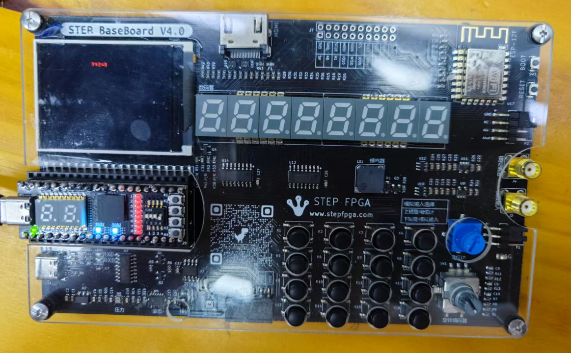
9-5=4

4*2=8
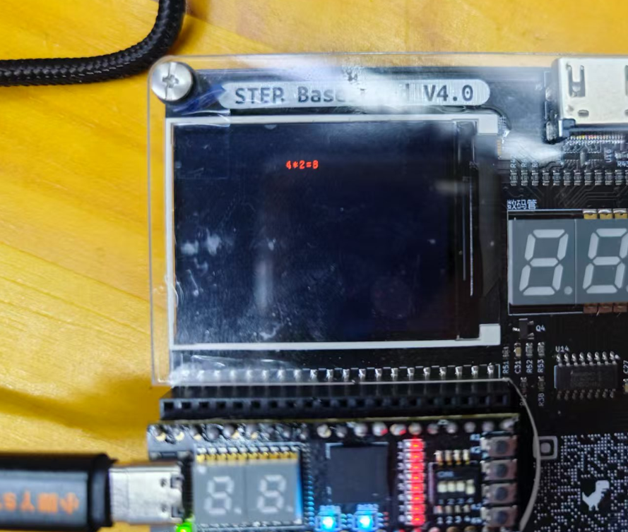
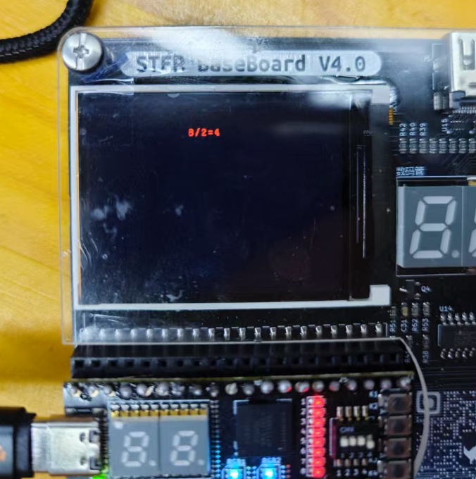
8/2=4
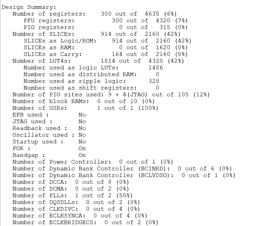
FPGA资源占用
遇到的难题和解决方法
- 语音识别准确率问题:
- 难题:百度合成的语音百度自己识别不了
- 解决方法:
- 进一步转化为标准格式
- 使用的工具为:ffmpeg-7.1-full_build
- USB通信后如何存储数据问题:
- 难题:上位机发送数据给FPGA后,FPGA如何接受,接收后如何进行计算
- 解决方法:
- 固定格式:
操作数1 + 操作符 + 操作数2,每个部分占用特定字节数 - 基于ASCII的字符串,如 "3+5",然后由
command_parser模块解析
- 固定格式:
- TFTLCD显示问题:
- 难题:例程中只有图片显示,没有文字显示
- 解决方法:
心得体会
通过本次语音控制计算器项目的开发,我深刻体会到了软硬件协同设计的重要性和挑战性。将大语言模型的自然语言处理能力与FPGA的高效并行计算特性相结合,不仅实现了功能完善的计算器系统,也展示了人机交互的新可能性。
在项目开发过程中,我学习到了许多宝贵经验:
- 跨领域知识整合:项目涉及语音识别、自然语言处理、FPGA设计、通信协议和显示控制等多个领域,需要综合运用各方面知识,这种跨领域整合能力对工程实践非常重要。
- 模块化设计思想:通过将系统分解为PC端语音处理、FPGA计算逻辑和显示控制等模块,使得系统开发更加清晰,调试更加方便,也为后续功能扩展提供了便利。
局限
最后一个星期开始做这个任务还是很勉强的,将功能砍了很多,只保留了个位数的计算器功能,大模型识别语音也改了,改成了大模型自己合成语音然后识别再发送。
致谢
最值得感谢的是Lingdajin,他已经将TFTLCD显示的项目写好了。
附件下载
cal_shou.zip
fpga
audio_recog.zip
上位机
团队介绍
个人
评论
0 / 100
查看更多
猜你喜欢
2024年寒假练 - 用小脚丫FPGA套件STEP BaseBoard V4.0实现简易计算器该项目使用了小脚丫FPGA套件STEP BaseBoard V4.0,实现了简易计算器的设计,它的主要功能为:实现八位十进制数的四则运算,可连续运算。
y268
598
2025寒假练 - 基于小脚丫FPGA STEP BaseBoard V4.0套件的语音控制计算器该项目使用了小脚丫FPGA STEP BaseBoard V4.0套件,实现了语音控制计算器的设计,它的主要功能为:大模型语音识别、计算过程和结果的显示。
鲍飞.
589
2025寒假练 - 基于小脚丫FPGA STEP BaseBoard V4.0套件实现语音控制计算机该项目使用了小脚丫FPGA STEP BaseBoard V4.0套件,Python语言,实现了语音控制计算机的设计,它的主要功能为:上位机识别语音,发送计算命令,FPGA接收命令进行计算,并在LCD屏幕上显示过程和结果。
Ling_da_jin
452