项目需求
- 上位机通过大模型识别手势
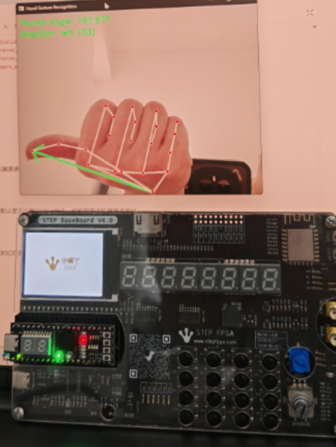
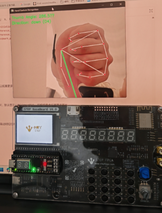
- 根据小脚丫核心板上的8个LED灯的变化状态来分别出显示手势识别的上下和左右
- 手势的信息在扩展板的TFTLCD上显示出来
- 小脚丫上三色灯的亮度显示接近传感器感知手势的远近
使用板卡:STEP Baseboard4.0底板+STEP MXO2 LPC核心板
项目介绍
一、项目概述
本项目构建了一套融合深度学习与FPGA的手势交互系统,主要包括上位机部分和FPGA控制板,上位机通过摄像头实时识别手手势和方向,通过串口传输到FPGA,FPGA上通过8个led灯中的四个显示手指所指方向,如果出现手势(握拳或者张开),FPGA将手势实时显示到LCD屏幕上,此外通过RPR-0521RS传感器检测距离,控制红绿光的占比,当手掌靠近时红灯亮提高,绿灯亮度降低。
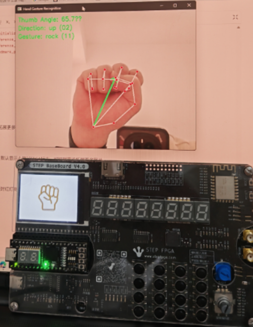
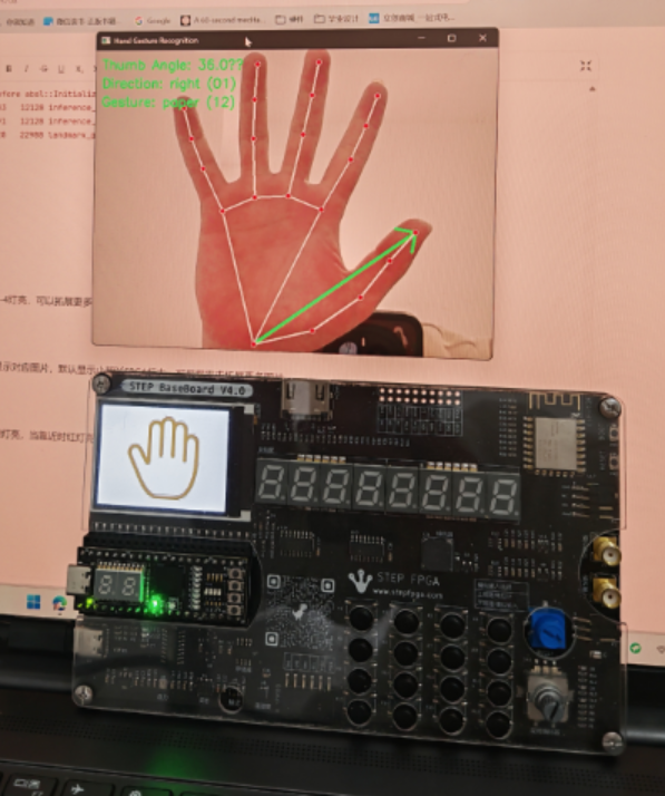
- 手势反馈:TFT-LCD实时显示手势类型
- 方向反馈:4路LED灯阵显示手势方向编码(上/下/左/右)
- 距离反馈:RGBLED亮度梯度反映手掌距离(绿→红渐变)
二、软硬件平台架构
2.1 硬件配置
- FPGA芯片采用Lattice LCMXO2-4000HC,包含4320个LUT逻辑单元,支持DDR存储器接口,内置2路PLL提供时钟管理
- 显示屏采用STEP BaseBoard V4.0上的320*240LCD显示屏,驱动芯片采用ST7789芯片,通过spi驱动
- 接近传感器采用STEP BaseBoard V4.0上的板载的RPR0521RS,通过I2C接口驱动,检测距离0-100mm可调
- 交互显示采用4个led和RGBled中的红绿灯,低电平有效,RGBled通过PWM占空比调节亮度
2.2 软件生态
FPGA开发环境:
- Lattice Diamond 3.12
- Synplify Pro综合工具
- ModelSim仿真平台
上位机开发栈:
- Python 3.8 + OpenCV 4.5
- MediaPipe 0.8.9.1手势识别库
- PySerial 3.5串口通信模块
三、系统设计方案
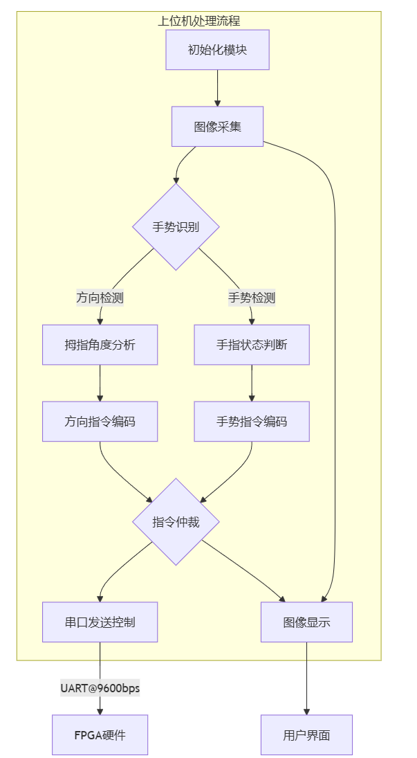
3.1上位机整体框架图
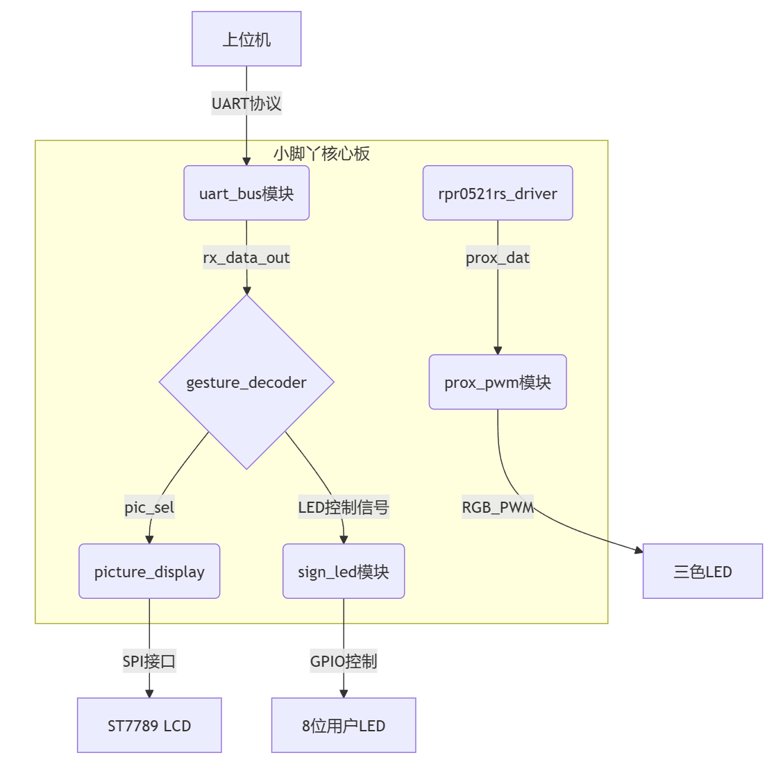
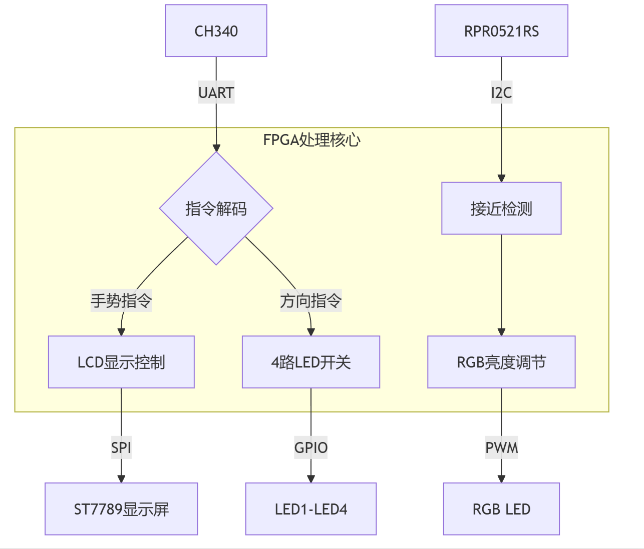
3.2FPGA端整体框架图
四、软件实现与核心代码
4.1 上位机处理流程
初始化模块
加载MediaPipe手势识别模型,配置串口参数(COM6,9600bps),创建指令映射字典
方向检测算法
通过手腕(0)与拇指指尖(4)关键点计算角度,采用arctangent函数获取360°方向角,划分四个方向区间
手势识别机制
分析五个手指的关节角度,当所有关节角度差<30°判定为伸直状态,综合伸直手指数量判断"rock"/"paper"
指令仲裁逻辑
优先发送手势指令(握拳0x11/布0x12),无手势时发送方向指令(上下左右0x01-0x04)
通信控制策略
采用300ms发送间隔,通过time.time()实现节流控制,避免串口数据过载
可视化界面
实时显示拇指方向矢量箭头,叠加角度数据和指令编码信息,保持30fps刷新率
import cv2
import mediapipe as mp
import math
import serial
import time

# 串口配置
SERIAL_PORT = 'COM6'
BAUDRATE = 9600

# 初始化MediaPipe
mp_hands = mp.solutions.hands
mp_drawing = mp.solutions.drawing_utils
hands = mp_hands.Hands(
    max_num_hands=1,
    min_detection_confidence=0.7,
    min_tracking_confidence=0.7)

# 初始化串口
try:
    ser = serial.Serial(SERIAL_PORT, BAUDRATE, timeout=1)
    print(f"串口 {SERIAL_PORT} 已连接")
except Exception as e:
    print(f"串口连接失败: {e}")
    ser = None

# 指令映射字典(移除剪刀)
COMMAND_CODE = {
   o "right": 0x01,
    "up": 0x02,
    "left": 0x03,
    "down": 0x04,
    "rock": 0x11,  # 握拳
    "paper": 0x12  # 布
}

# 发送间隔控制(秒)
SEND_INTERVAL = 0.3
last_send_time = 0


def get_thumb_direction(landmarks, frame_shape):
    """通过拇指方向识别手势"""
    wrist = landmarks[0]  # 手腕(0号关键点)
    thumb_tip = landmarks[4]  # 拇指指尖(4号关键点)

    h, w = frame_shape[:2]
    wx = int(wrist.x * w)
    wy = int(wrist.y * h)
    tx = int(thumb_tip.x * w)
    ty = int(thumb_tip.y * h)

    dx = tx - wx
    dy = ty - wy

    angle = math.degrees(math.atan2(-dy, dx))
    angle = (angle + 360) % 360

    return angle, (wx, wy, tx, ty)


def get_direction_from_angle(angle):
    """根据角度判断方向(使用拇指方向)"""
    if 45 <= angle < 135:
        return "up"
    elif 135 <= angle < 225:
        return "left"
    elif 225 <= angle < 315:
        return "down"
    else:
        return "right"


def get_finger_state(landmarks):
    """获取手指伸直状态(优化版)"""
    finger_states = {
        'thumb': False,
        'index': False,
        'middle': False,
        'ring': False,
        'pinky': False
    }

    finger_joints = {
        'thumb': [1, 2, 3, 4],
        'index': [5, 6, 7, 8],
        'middle': [9, 10, 11, 12],
        'ring': [13, 14, 15, 16],
        'pinky': [17, 18, 19, 20]
    }

    for finger in finger_states:
        tips = finger_joints[finger]
        p1 = landmarks[tips[0]]
        p2 = landmarks[tips[1]]
        p3 = landmarks[tips[2]]
        p4 = landmarks[tips[3]]

        # 通过关节角度判断是否伸直
        angle_diff = abs(math.degrees(math.atan2(p3.y - p2.y, p3.x - p2.x)) -
                         math.degrees(math.atan2(p2.y - p1.y, p2.x - p1.x)))
        finger_states[finger] = angle_diff < 30  # 调整阈值控制灵敏度

    return finger_states


def detect_gesture(finger_states):
    """改进的手势识别"""
    extended = sum(finger_states.values())

    # 握拳检测
    if extended == 0:
        return "rock"

    # 布检测
    if extended == 5:
        return "paper"

    return None


def send_command(command):
    """通过串口发送指令"""
    global last_send_time

    if ser is None:
        return

    current_time = time.time()
    if current_time - last_send_time < SEND_INTERVAL:
        return

    code = COMMAND_CODE.get(command, 0xFF)
    try:
        ser.write(bytes([code]))
        print(f"发送指令: {command} -> 0x{code:02X}")
        last_send_time = current_time
    except Exception as e:
        print(f"串口发送失败: {e}")


cap = cv2.VideoCapture(0)

while cap.isOpened():
    ret, frame = cap.read()
    if not ret:
        continue

    frame = cv2.flip(frame, 1)
    rgb_frame = cv2.cvtColor(frame, cv2.COLOR_BGR2RGB)
    results = hands.process(rgb_frame)

    direction = None
    gesture = None
    angle_info = None

    if results.multi_hand_landmarks:
        for hand_landmarks in results.multi_hand_landmarks:
            # 方向检测(基于拇指)
            angle, (wx, wy, tx, ty) = get_thumb_direction(
                hand_landmarks.landmark,
                frame.shape
            )
            direction = get_direction_from_angle(angle)
            angle_info = f"Thumb Angle: {angle:.1f}°"

            # 手势检测
            finger_states = get_finger_state(hand_landmarks.landmark)
            gesture = detect_gesture(finger_states)

            # 绘制检测结果
            cv2.arrowedLine(frame, (wx, wy), (tx, ty), (0, 255, 0), 3)
            mp_drawing.draw_landmarks(frame, hand_landmarks, mp_hands.HAND_CONNECTIONS)

    # 发送指令(手势优先)
    if gesture:
        send_command(gesture)
    elif direction:
        send_command(direction)

    # 显示信息
    info_lines = []
    if angle_info:
        info_lines.append(angle_info)
    if direction:
        info_lines.append(f"Direction: {direction} ({COMMAND_CODE[direction]:02X})")
    if gesture:
        info_lines.append(f"Gesture: {gesture} ({COMMAND_CODE[gesture]:02X})")

    for idx, line in enumerate(info_lines):
        cv2.putText(frame, line, (10, 30 + 30 * idx),
                    cv2.FONT_HERSHEY_SIMPLEX, 0.7, (0, 255, 0), 2)

    cv2.imshow('Hand Gesture Recognition', frame)

    if cv2.waitKey(10) & 0xFF == ord('q'):
        break

# 释放资源
cap.release()
cv2.destroyAllWindows()
hands.close()
if ser is not None:
    ser.close()
4.2 FPGA关键模块
时钟管理模块:
系统输入时钟clk为12MHz,各模块时钟如下:
显示逻辑时钟:50MHz(PLL),相位抖动控制在±5%范围内
UART通信时钟:波特率9600(计数器分频)
I2C通信时钟:400khz
PWM调光频率:3khz
LCD显示模块:
lcd屏幕为240x320分辨率,16位色深(RGB565),通过读取ram中数据显示图片,ram地址位0-960,每张图片包括240*320位,每一位中0代表背景色,1代表前景色,通过切换读取地址更换图片
//主模块
module picture_display
(
input clk ,
input rst_n ,
input [1:0] pic_sel , // 图片选择信号
output lcd_rst ,
output lcd_blk ,
output lcd_dc ,
output lcd_sclk ,
output lcd_mosi ,
output lcd_cs
endmodule
// 根据pic_sel_out选择不同的图片地址
always@(posedge sys_clk or negedge sys_rst_n)
if(!sys_rst_n)
rom_addr <= 'd0;
else if(cnt_rom_prepare == 'd1) begin
case(pic_sel_out)
2'b01: rom_addr <= cnt_length_num + 10'd320; // 第二张图片 320-639
2'b10: rom_addr <= cnt_length_num + 10'd640; // 第三张图片 640-959
default: rom_addr <= cnt_length_num; // 第一张图片 0-319
endcase
end
接近检测模块:
接近检测通过RPR0521RS接近传感器实现,通过I2c接口(400kHz快速模式)读取prox_dat,通过其低12位计算RGBLED中的红灯和绿灯的PWM占空比,实现靠近红灯变亮、绿灯变暗
module prox_detect(
        input               clk,
        input               rst_n,

        output          i2c_scl,    //I2C时钟总线
        inout           i2c_sda,    //I2C数据总线
        output  [5:0]   pwm_led     //led灯
    );
// (提取低12位)
always @(posedge clk or negedge rst_n) begin
    if(!rst_n) begin
        stable_prox <= 12'h0;
    end else begin
        // 取三个采样值的中间值的低12位
        if((prox_buf[0][11:0] >= prox_buf[1][11:0] && prox_buf[0][11:0] <= prox_buf[2][11:0]) ||
           (prox_buf[0][11:0] <= prox_buf[1][11:0] && prox_buf[0][11:0] >= prox_buf[2][11:0]))
            stable_prox <= prox_buf[0][11:0];
        else if((prox_buf[1][11:0] >= prox_buf[0][11:0] && prox_buf[1][11:0] <= prox_buf[2][11:0]) ||
                (prox_buf[1][11:0] <= prox_buf[0][11:0] && prox_buf[1][11:0] >= prox_buf[2][11:0]))
            stable_prox <= prox_buf[1][11:0];
        else
            stable_prox <= prox_buf[2][11:0];
    end
end
LED控制模块:
方向指示LED控制:4路独立LED,低电平有效
接近指示RGB调光控制:prox_dat,通过prox_dat低12位计算RGBLED中的红灯和绿灯的PWM占空比,控制亮度
//方向指示LED控制
module sign_led (
input [7:0] in, // 通用输入端口
output reg [7:0] out // 通用输出端口
);
always @ (in) begin
case(in)
8'h01: out = 8'b11111110; // 低有效译码
8'h02: out = 8'b11111101;
8'h03: out = 8'b11111011;
8'h04: out = 8'b11110111;
8'h05: out = 8'b11101111;
8'h06: out = 8'b11011111;
8'h07: out = 8'b10111111;
8'h08: out = 8'b01111111;
default: out = 8'b11111111; // 安全默认值
endcase
end
endmodule
//RGBLED模块
pwm_led u_pwm (
.clk (clk),
.rst_n (rst_n),
.brightness (stable_prox), // 直接连接稳定的12位数据
.pwm_led (pwm_led)
);
// PWM周期计数器(0-3999)
reg [11:0] pwm_counter;
// 在模块顶部添加
wire [11:0] safe_brightness = (brightness > 12'd3999) ? 12'd3999 : brightness;
always @(posedge clk or negedge rst_n) begin
if (!rst_n) begin
pwm_counter <= 12'd0;
end else begin
pwm_counter <= (pwm_counter == 12'd3999) ? 12'd0 : pwm_counter + 1'b1;
end
end
// 比较器生成PWM信号
wire duty_cycle = (pwm_counter < brightness) ? 1'b1 : 1'b0;
// 6路LED输出
assign pwm_led[0]=~duty_cycle;
assign pwm_led[1]=duty_cycle;
assign pwm_led[2]=1;
assign pwm_led[3]=1;
assign pwm_led[4]=1;
assign pwm_led[5]=1;
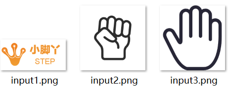
4.3图片信息生成
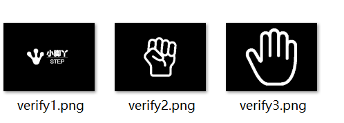
图片信息生成及验证程序:
该程序将所需的三张图片转换成位图信息,并根据位图信息生成验证图片
import os
import glob
from PIL import Image, ImageEnhance, ImageOps
import numpy as np


# -------------------- 转换部分 --------------------
def convert_images():
    # 自动检测input文件
    input_files = sorted(glob.glob("input*.png"))
    if not input_files:
        print("未找到input*.png文件")
        return

    for idx, input_file in enumerate(input_files, 1):
        output_bin = f"output{idx}.bin"
        output_h = f"output{idx}.h"

        try:
            # 图像处理流程
            img = Image.open(input_file).convert("L")
            img = ImageEnhance.Contrast(img).enhance(2.0)
            img.thumbnail((320, 240), Image.Resampling.LANCZOS)

            canvas = Image.new("L", (320, 240), 0)
            canvas.paste(img, (
                (320 - img.width) // 2,
                (240 - img.height) // 2
            ))

            img_array = np.array(canvas)
            thresh = max(np.mean(img_array) - np.std(img_array) / 2, 40)
            bin_img = img_array > thresh

            # 生成二进制
            byte_array = bytearray()
            for row in bin_img:
                for i in range(0, 320, 8):
                    byte = sum(row[i + b] << (7 - b) for b in range(8) if i + b < 320)
                    byte_array.append(byte)

            # 保存文件
            with open(output_bin, "wb") as f:
                f.write(byte_array)

            with open(output_h, "w") as f:
                f.write(f"const uint8_t output{idx}[] = {{\n")
                f.write(",".join(f"0x{b:02x}" for b in byte_array))
                f.write("\n};\n")

            print(f"生成成功:{output_bin} | {output_h}")

        except Exception as e:
            print(f"处理 {input_file} 失败:{str(e)}")


# -------------------- 验证部分 --------------------
def verify_bin_files():
    bin_files = sorted(glob.glob("output*.bin"))
    if not bin_files:
        print("未找到output*.bin文件")
        return

    for bin_file in bin_files:
        # 提取编号
        num = bin_file.replace("output", "").replace(".bin", "")
        verify_png = f"verify{num}.png"

        try:
            # 解码验证
            with open(bin_file, "rb") as f:
                data = f.read()

            img = Image.new('1', (320, 240))
            pixels = img.load()

            for y in range(240):
                row = data[y * 40: (y + 1) * 40]
                for byte_idx, byte in enumerate(row):
                    x_start = byte_idx * 8
                    for bit in range(7, -1, -1):
                        x = x_start + (7 - bit)
                        if x < 320:
                            pixels[x, y] = (byte >> bit) & 0x01

            img.save(verify_png)
            print(f"验证文件生成:{verify_png}")

        except Exception as e:
            print(f"解码 {bin_file} 失败:{str(e)}")


if __name__ == "__main__":
    print("======== 开始转换 ========")
    convert_images()

    print("\n======== 开始验证 ========")
    verify_bin_files()

    print("\n操作完成!请检查以下文件:")
    print("转换文件:", glob.glob("output*.*"))
    print("验证文件:", glob.glob("verify*.png"))
bin文件转换ram程序:
该程序将生成的bin文件转换成FPGA需要的ram文件,用于查找图片信息
import glob
def bin_to_verilog(bin_files, verilog_file):
    # 初始化存储所有图片的转置数据
    transposed_data = []

    for bin_file in bin_files:
        with open(bin_file, 'rb') as b:
            data = b.read()

        # 创建 240x320 的布尔值矩阵
        img_matrix = [[0 for _ in range(320)] for _ in range(240)]

        # 解压二进制数据到矩阵
        byte_index = 0
        for row in range(320):  # 每行 40 字节
            for col in range(0, 320, 8):  # 每个字节包含 8 位
                byte = data[byte_index]
                for bit in range(7, -1, -1):  # 从高位到低位提取位
                    if col + (7 - bit) < 320:  # 防止越界
                        img_matrix[col + (7 - bit)][row] = (byte >> bit) & 0x01
                byte_index += 1

        # 转置矩阵
        transposed_img = list(map(list, zip(*img_matrix)))  # 转置操作
        transposed_data.extend(transposed_img)

    # 写入 Verilog 文件
    with open(verilog_file, 'w') as f:
        f.write("`timescale 1 ns / 100 ps\n")
        f.write("module pic_ram (address, q);\n\n")
        f.write("    input wire [9:0] address;  // 地址宽度为 10 位\n")  # 支持 960 行
        f.write("    output reg [239:0] q;      // 每行数据为 240 位\n\n")
        f.write("    always @ (*) begin\n")
        f.write("        case(address)\n")

        for i, row in enumerate(transposed_data):
            bit_string = ''.join(str(bit) for bit in row[:240])  # 截取前 240 位
            f.write(f"            10'd{i} : q = 240'b{bit_string};\n")

        # 默认值处理
        f.write("            default: q = 0;\n")
        f.write("        endcase\n")
        f.write("    end\n\n")
        f.write("endmodule")

if __name__ == "__main__":
    # 自动检测output*.bin文件
    bin_files = sorted(glob.glob("output*.bin"))
    if not bin_files:
        print("未找到output*.bin文件")
    else:
        verilog_file = "pic_ram.v"
        bin_to_verilog(bin_files, verilog_file)
        print(f"生成成功:{verilog_file}")
五、功能演示
5.1 图片生成效果
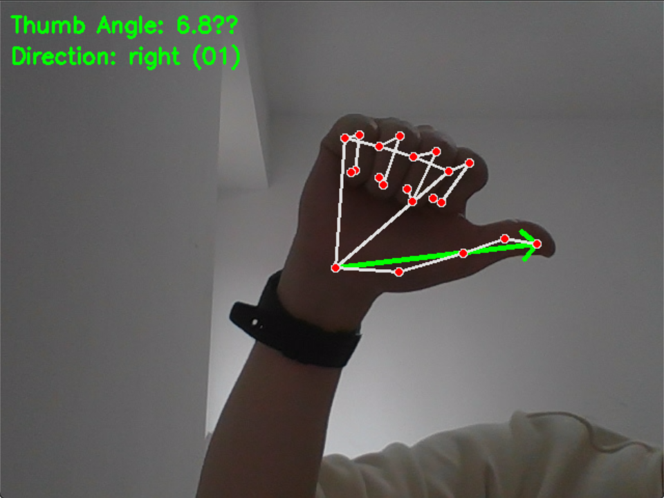
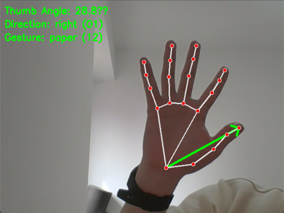
5.2 上位机识别效果
识别拇指方向和手势如下图

5.3 FPGA显示效果
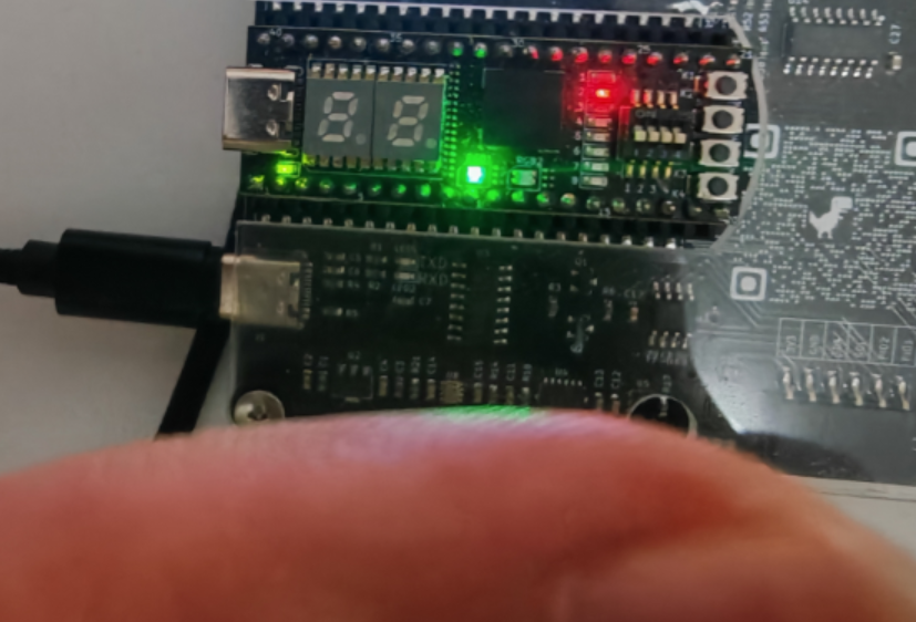
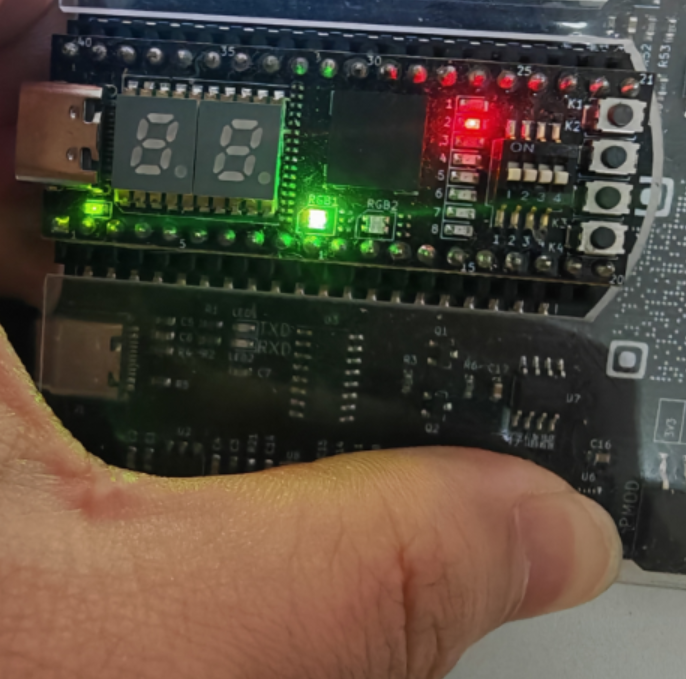
方向识别
当方向位右上左下时,分别对应1-4灯亮,可以拓展更多角度

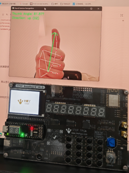
手势显示
当识别到张开或者握拳时,显示对应图片,默认显示小脚丫FPGA标志,可根据需求拓展更多图片
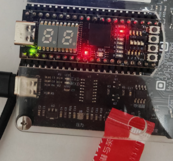
距离反馈
当手离距离传感器较远时,绿灯亮,当靠近时红灯亮
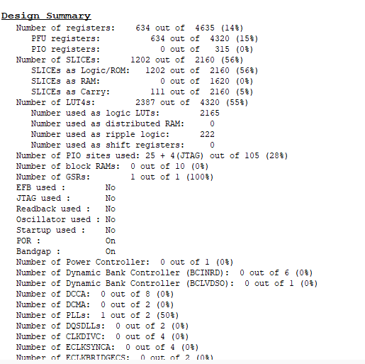
5.4 FPGA资源消耗报告
- 寄存器使用率:14% (634/4635)
- SLICE利用率:56% (1202/2160)
- LUT4利用率:55% (2387/4320)
六、项目难点与解决方案
LCD驱动开发
难点:面对ST7789芯片手册中300+页的寄存器描述(如MV[3:0]显存扫描方向配置),无法快速定位关键参数。初期直接发送只发送一次初始化命令后出现图像偏移问题。
解决方案:通过分析底板例程的lcd_init()函数,将原来的流程改成每次更换图片后都重新进行整个刷新流程。
时序逻辑同步顽疾
典型问题:UART接收到的信号与LCD显示图片的信号在数据跨时钟域传输时,出现时间同步问题。
解决方案:采用三级寄存器同步链消除亚稳态:
七、心得体会和建议
通过这次活动,我完成了从对FPGA一窍不通到能够基于例程去做一个项目的蜕变,了解verilog语言和FPGA项目开发的全流程,也学习了基础外设的使用方法,掌握了一定的debug能力和程序设计能力,希望以后能够有更多的教程讲解一些FPGA开发过程中的难点痛点,比如时序同步设计、复杂状态机设计,能够出更多的开源项目把整个板子都利用起来。

 siman
siman